
In our last tutorial, we designed a circuit to detect and measure a button bounce. However, there was no way to see the debounce information outside the design. In this tutorial, we will add the ability to see the debounce information and create a self-checking test bench to verify our design.
Let’s See Some Output
One thing that would be really helpful is to know what is going on with the states. We have the triggered_rise and triggered_fall signals, which indicate that the state machine saw a button rise or a button fall. Once set, these signals will stay on until we return to the idle state. It would also be useful to have a signal which indicate that the state machine is in the idle state. Let’s do that now:
wire waiting = state == idle_state;Then we can take over the LED outputs to show us some status information. Like this:
  always @(posedge clk)
    led <= {btnc_fall,btnc_rise,waiting,triggered_fall,triggered_rise};
If you haven’t seen the syntax before, the curly braces tell Verilog to concatenate the signals inside the braces together. Basically, it places the signals into a larger bus. We’ll assign this bus to the led outputs. Our real challenge, however, is to display the values of the period0 and period1 registers. To do this, we will use the switches to look at different bytes within the values of the registers. This is similar to how the stopwatch could look at hundredths, seconds, minutes, and hours.
We declare an 8-bit register called ssd_byte and use a case statement based on the switch inputs to select which part of the pattern0 and pattern1 registers we want to look at. Here’s my version:
  reg [7:0] ssd_byte;
  always @(*)
    case (1'b1)
      switch[5]: ssd_byte = period1[$clog2(bounce_limit)-1:16];
      switch[4]: ssd_byte = period1[15:8];
      switch[3]: ssd_byte = period1[7:0];
      switch[2]: ssd_byte = period0[$clog2(bounce_limit)-1:16];
      switch[1]: ssd_byte = period0[15:8];
      switch[0]: ssd_byte = period0[7:0];
      default: ssd_byte = 0;
    endcase
Notice how we need to limit the most significant byte of the period registers to $clog2(bounce_limit). This is because the registers don’t have a full 24 bits of precision. If we were to use just 23:16, the synthesis tool would complain that we are indexing outside the range of the period0 and period1 registers. The simulator, on the other hand, doesn’t care if we do that.
Now, we need to assign the digit signal based on the ssd_byte output from the switch statement. Also, note that we use the count[0] as the mux select to keep the ssd and ssdcat signals aligned. Like this:
assign digit = count[0] ? ssd_byte[7:4] : ssd_byte[3:0];Start a simulation and… it won’t compile. The problem is that we defined bounce_limit to be 10*ms_limit. And in synthesis ms_limit is 100000, so bounce_limit is 10000000, and $clog2(bounce_limit) is 20. This gives the synthesis tool the range 19:16, which is just great. However, in simulation we overrode the ms_limit parameter with a value of 100. This means that bounce_limit then has a value of 1000, and $clog2(bounce_limit) has a value of only 10. So, we are telling the simulator that it should index into the period registers with an index of 9:16. This is backwards from the way we declared the registers, so we get an error.
One Minor Hitch
What to do? Ideally, what we want is to have the ms_limit parameter that the test bench can override for simulation purposes, and a second ms_limit value which it doesn’t override. Then, we can use the non-overridden parameter to size our registers, and the overridden parameter to limit our counters. To do this, we declare a new parameter that we will call default_ms_limit and set it to 100000, then use that parameter as the default value of the ms_limit parameter. So go back to the parameter list of the top.v file and change it to look like this:
  parameter default_ms_limit = 100000,
  parameter ms_limit = default_ms_limit
Then modify your bounce_limit and period declarations to look like this:
  localparam bounce_milliseconds = 10;
  localparam bounce_limit = bounce_milliseconds*ms_limit;
  localparam default_bounce_limit = bounce_milliseconds*default_ms_limit;
  reg [$clog2(default_bounce_limit)-1:0] bounce_count = 0;
  wire bounce_limit_reached = bounce_count == bounce_limit-1;
  reg [$clog2(default_bounce_limit)-1:0] period0 = 0;
  reg [$clog2(default_bounce_limit)-1:0] period1 = 0;
Notice how I have made a new parameter called bounce_milliseconds, which defines the number of milliseconds we want the bounce counter to count. Then I used that parameter to define bounce_limit as before, but also used it to define a default_bounce_limit parameter. Then I used the default_bounce_limit parameter to define bounce_count, period0, and period1.
Finally, I can modify the case statement to use the default_bounce_limit parameter which will not change between simulation and synthesis.
  reg [7:0] ssd_byte;
  always @(*)
    case (1'b1)
      switch[5]: ssd_byte = period1[$clog2(default_bounce_limit)-1:16];
      switch[4]: ssd_byte = period1[15:8];
      switch[3]: ssd_byte = period1[7:0];
      switch[2]: ssd_byte = period0[$clog2(default_bounce_limit)-1:16];
      switch[1]: ssd_byte = period0[15:8];
      switch[0]: ssd_byte = period0[7:0];
      default: ssd_byte = 0;
    endcase
Simulation
Let’s get back to simulating our design. Now that we can see the digits of the period registers, we should be able to also verify that they match the way we bounced the button.
As with our other test bench in Tutorial 6, we will need to recover the value of the digits from the seven segment display output from our FPGA. We use the same code as before:
  wire [7:0] digits;
  ssd_digit PmodSSD0
    (
     .enable(~ssdcat),
     .ssd(ssd),
     .value(digits[3:0])
     );

  ssd_digit PmodSSD1
    (
     .enable(ssdcat),
     .ssd(ssd),
     .value(digits[7:4])
     );
Also, be sure to add the source to the ssd_digit.v file to your simulation. From th eProject Manager, select Add Sources to add a simulation source. Then select the module from Tutorial 6. Be sure to check the box indicating you want Vivado to copy the file into the project area.
Next, we will create a task called read_period which can read the period registers. This task will do it the same way you’d do it on the actual FPGA board. To read period0, it flips switch 0 to look at the least significant byte, then switch 1 to look at the next byte, then switch 2 to look at the third byte. It then builds the final value from the three bytes. Let’s first just fill in the declaration of the task. Later we will fill in the body.
The task will take an input indicating which period register to read, and produce an output which is the value of the register. Also, the task uses a local variable called base which stores the switch for the least significant byte for the desired period register. Here is the task declaration:
  task read_period;
    input which;
    output integer value;
    integer base;
    begin

    end
  endtask
For the body of the task (the part between begin and end), we first set the base variable to 3*which. This will make it either 0 or 3. Then, we set the switches to zero, except the switch pointed to by base (0 or 3). Next we need to wait for ssdcat to transition twice. This will either be low-to-high and then high-to-low, or high to low and then low to high. This makes sure that both of the ssd_digit modules get to latch the updated digits. Here is the code for reading the least significant byte:
      base = which*3;
      switch <= 0;
      switch[base] <= 1;
      @(ssdcat);
      @(ssdcat);
      repeat (10) @(posedge clk);
      value = digits;
Notice how we set all the bits of switch to zero, then set the one we want high on the following line. Then the line @(ssdcat) waits for a rising or falling edge on ssdcat. The same line again waits for another edge. This way, we are sure to see ssdcat transition high and low. Now, there’s a wait for ten clocks to allow the ssd_digit modules to update their outputs. Then, we set value equal to the ssd_digit modules digits output. Now let’s add the code to read the other digits:
      switch <= 0;
      switch[base+1] <= 1;
      @(ssdcat);
      @(ssdcat);
      repeat (10) @(posedge clk);
      value = value | digits<<8;
      switch <= 0;
      switch[base+2] <= 1;
      @(ssdcat);
      @(ssdcat);
      repeat (10) @(posedge clk);
      value = value | digits<<16;
Now for the actual test code. First we need to declare a variable to hold the period values we read. Since there are two values I am going to use an array to hold them:
integer period[1:0]Then, we’ll use an initial block to make everything run. The block will have an initial waiting period to let everything get up and running. Then there’s a press of the center button with some bounce. Then another pause followed by reading the two period registers, and then we clear the trigger. I follow that with the same thing, but releasing the button. Then a final pause and we finish the simulation. Here is my code:
  initial
    begin
      repeat (10) @(posedge clk);

      press_button(4,100,100);
      repeat (10) @(posedge clk);
      read_period(0,period[0]);
      read_period(1,period[1]);
      clear_trigger;

      release_button(4,200,50);
      repeat (10) @(posedge clk);
      read_period(0,period[0]);
      read_period(1,period[1]);
      clear_trigger;

      repeat (10) @(posedge clk);
      $finish;
    end
If we run the simulation and add the signals of interest to the waveform I get the following:
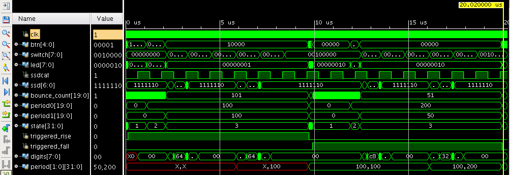
Notice how you can see the period array change to 100,100 around 10µs? That’s immediately before we clear the state machine. Then, right before the end of the simulation, we see it change again to 50,200. There isn’t room on the waveform to display the values, but you can see it in the value column to the left.
Self-Checking
To make a self-checking test, we first need to declare our number of errors and number of checks counters.
  integer num_checks = 0;
  integer num_errors = 0;
Then, we want to declare a task which will perform a button press or release and checks that the measured bounce period matches the bounce periods the test used. We will call this task test_button. It’s going to need variables to hold the expected and measured period values. Here is the task declaration with an empty body:
  task test_button;
    input integer button;
    integer period[1:0];
    integer expected_period[1:0];
    begin
    end
  endtask
In the body of the task, we need to set some expected values for the period registers. We will generate random values for these. The values must be less than the maximum of the bounce count in the top module. The best thing to do is to make use of the bounce_limit parameter in the top module. That way, if the parameter changes, our test bench will still be correct. This illustrates an important principal of only specifying a piece of information in one place. Here is that code:
      expected_period[0] = {$random}%(top.bounce_limit-10)+10;
      expected_period[1] = {$random}%(top.bounce_limit-10)+10;
These two lines of code are just chock full of gems. First the term top.bounce_limit reaches into the instance called top and gets the value of its bounce_limit parameter. In general, we don’t want the test looking into the modules it is testing, because if you do a gate level simulation, all the internals are different. However, the parameters will never change so are OK to look at. You can also see that we call the $random function to return a random value. This function returns a 32-bit signed number. We will use the modulo operator % to reduce the value returned by $random down to something smaller. If we use the expression a%b, then the result is what you get when you divide a by b and take the remainder. I am looking for a random number between 10 and top.bounce_limit. In our simulation, this is between 10 and 999. So we take our random number and find the remainder when dividing by 990. This gives a number between 0 and 989. We then add 10 to that to get a value between 10 and 999. So why am I really using {$random} instead of just $random? The answer is that the modulo operator can do funny things when you give it a negative number. What is -7%10? Why 3 of course! Because 10*-1+3 = -7. A different computer might tell you -7 because 10*0-7 = -7. By placing a signed 32-bit value inside a concatenation, we get an unsigned 32-bit value. That way we don’t get any funny business.
Next we need to press or release the button, depending on its current state. Here’s the code to do that:
      if (btn[button])
	begin
	  release_button(button,expected_period[0],expected_period[1]);
	  wait(led[1]);
	end
      else
	begin
	  press_button(button,expected_period[0],expected_period[1]);
	  wait(led[0]);
	end
We include a wait statement which causes the simulator to wait until the appropriate LED lights up.
Then we need to read the period values and compare them to the expected results:
      read_period(0,period[0]);
      read_period(1,period[1]);
      num_checks = num_checks+1;
      if (period[0] != expected_period[0])
	begin
	  $display("*** ERROR: period[0] value %0d does not match expected value of %0d",
		   period[0],expected_period[0]);
	  num_errors = num_errors+1;
	end
      num_checks = num_checks+1;
      if (period[1] != expected_period[1])
	begin
	  $display("*** ERROR: period[1] value %0d does not match expected value of %0d",
		   period[1],expected_period[1]);
	  num_errors = num_errors+1;
	end
And finally, we need to clear the trigger condition by calling the clear_trigger task.
clear_trigger;Overall Control
The actual initial block which says what to do is really quite simple. Here it is:
  initial
    begin
      repeat (10) @(posedge clk);
      repeat (100) test_button(4);
      repeat (10) @(posedge clk);
      $display("Simulation complete at time %0fns.",$realtime);
      if (num_errors > 0)
	$display("*** Simulation FAILED %0d/%0d",num_errors,num_checks);
      else
	$display("*** Simulation PASSED %0d/%0d",num_errors,num_checks);
      $finish;
    end
When I run this, I see the magic results I am looking for:
Simulation complete at time 1796240.000000ns.
*** Simulation PASSED 0/200
If you look at the waveform, you get a pretty good idea of the level of activity you get with this test. To be thorough, we should probably also give some transitions where the button doesn’t bounce and make sure that case works as well– but I think you get the point.
Using the Design
Now build the design and download it to your board. What values to you get for the period counters? Does the button bounce more often when it is pressed or released? We are only investigating the first bounce. How would you modify the design to see if it bounces more than once? Is the 10ms bounce limit that we use for the bounce counter a good choice? Would it be safe to make it smaller?
Here are the files I have for this tutorial.
Pingback: Lab 9 and 10: The Bounce Measure – tranminhhai