
In this tutorial, we will use the Digilent Pmod rotary encoder– PmodENC. Our first design will just increment or decrement an 8-bit counter depending on which way the encoder knob is rotated.
Using the Rotary Encoder
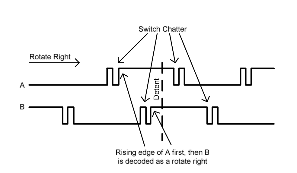 The PmodENC rotary encoder from Digilent is really quite simple to use. It has four inputs to the FPGA: a sliding switch input from a separate switch on the module, a push button input which is high when the shaft is pressed in, and an a and b input which come from the rotary shaft. Basically, the shaft has the effect of pressing two switches whenever it is rotated. The switch inputs are called a and b. When the switch is rotated one direction, the switch a changes state before switch b. Rotate the other way and b will lead a.
In order to read the encoder, we will first debounce the inputs using our debounce circuit from tutorial11. Then we look for the rising edge of a. This will let us know that the shaft was turned. The value of the b input when a rises will tell us the direction the shaft was rotated. It is tempting to use the a input as a clock in this situation. However, doing so will cause lots of problems. The synthesis and place and route tools need to know the timing relationships between all the signals in the design. The tools need to make sure that the design will work at the specified clock frequency. By creating a new clock we complicate this timing analysis.
Constraints
We need to add some new constraints to our top.xdc file. These specify the input pin locations for the four new inputs and the IO type. Here are the new constraints.
set_property IOSTANDARD LVCMOS33 [get_ports enc_a]
set_property IOSTANDARD LVCMOS33 [get_ports enc_b]
set_property IOSTANDARD LVCMOS33 [get_ports enc_btn]
set_property IOSTANDARD LVCMOS33 [get_ports enc_sw]
set_property PACKAGE_PIN AB7 [get_ports enc_a]
set_property PACKAGE_PIN AB6 [get_ports enc_b]
set_property PACKAGE_PIN Y4 [get_ports enc_btn]
set_property PACKAGE_PIN AA4 [get_ports enc_sw]
Design
We are going to create a simple design that display the value of an 8-bit register on the seven segment display. The counter will increment when we rotate the encoder knob clockwise and decrement when we rotate it counterclockwise. We will also use the same signals as previous designs. Here is the module declaration:
`timescale 1ns / 1ns
module top
#(
  parameter default_ms_limit = 100000,
  parameter ms_limit = default_ms_limit
) (
   input clk,
   input [7:0] switch,
   input [4:0] btn,
   output reg [7:0] led,
   output reg [6:0] ssd,
   output reg ssdcat,

   input enc_a,
   input enc_b,
   input enc_sw,
   input enc_btn
   );
Notice how I’ve prefixed all the encoder signals with enc. This helps us keep things straight in the rest of the code. Consistency with naming is often helpful when dealing with lots of signals.
Debounce
In the design we will debounce all the button and switch inputs as well as the inputs from the encoder. We have eight switch inputs, five button inputs, and four encoder inputs for 17 inputs total. For each input our debounce circuit creates a debounced output as well as a rise and fall output. We will need to declare the debounced, rise, and fall signals for each of the debounce inputs. I used suffixes of db, rise, and fall. Here are the wire declarations:
  wire [7:0] switch_db;
  wire [4:0] btn_db;
  wire enc_a_db;
  wire enc_b_db;
  wire enc_sw_db;
  wire enc_btn_db;

  wire [7:0] switch_rise;
  wire [4:0] btn_rise;
  wire enc_a_rise;
  wire enc_b_rise;
  wire enc_sw_rise;
  wire enc_btn_rise;

  wire [7:0] switch_fall;
  wire [4:0] btn_fall;
  wire enc_a_fall;
  wire enc_b_fall;
  wire enc_sw_fall;
  wire enc_btn_fall;
Next we instantiate the debounce module. We will set the width parameter to 17. We use the Verilog concatenation notation to join all our signals into a single 17-bit bus for the input and outputs of the module.
  debounce
    #(
      .width(17),
      .bounce_limit(ms_limit*3)
      )
  debounce
    (
     .clk(clk),
     .switch_in({enc_a,enc_b,enc_sw,enc_btn,
		 btn,switch}),
     .switch_out({enc_a_db,enc_b_db,enc_sw_db,enc_btn_db,
		  btn_db,switch_db}),
     .switch_rise({enc_a_rise,enc_b_rise,enc_sw_rise,enc_btn_rise,
		   btn_rise,switch_rise}),
     .switch_fall({enc_a_fall,enc_b_fall,enc_sw_fall,enc_btn_fall,
		   btn_fall,switch_fall})
     );
Encoder
We declare an 8-bit register that will hold the value controlled by the encoder. This will increment the register when the encoder turns clockwise, and decrement it when it turns counterclockwise.
  reg [7:0] enc_byte = 0;
  always @(posedge clk)
    if (enc_a_rise)
      if (!enc_b_db)
	enc_byte <= enc_byte-1;
      else
	enc_byte <= enc_byte+1;
I have also decided to put the seven segment display driver in its own module. This makes the top level design a little cleaner. I won’t go into detail on this, but you can download the file from the link at the end of this tutorial. Here is the code to instantiate the seven segment driver though.
  ssd
    #(ms_limit)
  sse
    (
     .clk(clk),
     .value(enc_byte),
     .ssd(ssd),
     .ssdcat(ssdcat)
     );
Lastly we need to drive the LED outputs. I have chosen to drive two of the LEDs from the a and b signals from the encoder. You can watch how these operate as you turn the display slowly.
  always @(posedge clk)
    led <= {switch_db[7:2],enc_b_db,enc_a_db};
Other Features
Try extending the design to reset enc_byte whenever the encoder button is activated by pressing the encoder shaft down. Or even better, can you make the count increment faster when the shaft is pressed?
Files
Here are the files I have for this tutorial.
Please check top.v in this tutorial. I believe the call to ‘sse’ is a typo, should be ‘ssd’
Actually, the top.v correctly instantiates the ssd module. It just has a typo where the instance name is sse when ssd would be more appropriate. I will fix it though.
April 20, 2013Great tutorial. Thanks!I did go the extra mile and add the reirstoss and caps to my Arduino attempt. The proper filtering on there made a lot of difference (my rotary encoder is 12 steps). Moved it all to freeSoC (without the reirstoss and caps) and, er, it worked a lot better. The glitch filter that’s just there, does as least as well as a bunch of discrete components. Awesome.Jon, that was a great tutorial..It was nicely paced, and you didn’t bore me with watching you plug wires in or write code PSoC Creator tells me where stuff goes, code is, er, code. Nice job!For the record, I know nothing. I’m a software person. Had never even thought about electronics until about a year ago. Just making up for lost time, I guess Dave
Hello Pete Johnson,
I am sorry for this somewhat irrelevant question.
The “PmodENC: Rotary Encoder” (Feb. 15, 2016) is currently out of stock. I find another Rotary Encoder on Amazon.co.jp ( I’m in Japan), but this one has 5 pins (no BTN). Voltage probably is compatible (3.0-5.3V).
Can I use the one form amazon.co.jp instead of one from Diligent? are they interchangeable?
http://www.amazon.co.jp/Waveshare-Encoder-Sensor-Development-Rotation/dp/B00NL7PVGM/ref=sr_1_1?ie=UTF8&qid=1455503468&sr=8-1&keywords=rotary+encoder
(sorry this is in Japanese).
Thank you!
Hello Pete Johnson,
Could you please suggest an affordable RF module connecting to our ZedBoard?
I am ordering PmodSSD seven segment display,15 dollars, but the shipping fee (US–>JP) is 75 dollars. So I would like to buy RF module together with the display.
Thank you!!!
That one looks like it could be made to work. You may have to change the pin constraints to match the different pinout. And you might need to connect it with jumper wires. I didn’t check if power and ground were on the right pins.
I don’t know what requirements you have for your RF module. If you can’t use the PmodSSD then you should be able to substitute others that are more available in Japan. Or you could make your own. There is not much to it.