
AXI4 Streaming
In this final part of tutorial 18, we’re going to add an AXI4 streaming interface to the I2S receiver. This interface will allow the receiver to play with the Vivado IP tool flow.
AXI4 Streaming Overview
The ARM AXI4 standard has two types of interfaces. First, there’s the memory mapped AXI4 and AXI4-Lite interfaces, of which we have seen the AXI4-Lite before. These interfaces implement a microprocessor bus interface. Transactions are reads and writes of data to memory addresses.
Streaming interfaces like the AXI4 Streaming interface are different. They don’t have a concept of addresses, and data transfers can only occur in one direction. They’re meant to handle a stream of information– sort of like a network packet, or audio data like that produced by our I2S receiver. A streaming interface can either be a master or a slave. Master interfaces generate data that are sent to slaves. So, our I2S receiver is a I2S slave interface– it receives data from an I2S master, so therefore it is an AXI4 Streaming master interface. In tutorial 19 we will design a I2S transmitter interface which is an I2S master and will have an AXI4 slave interface. We will be able to extend our audio loopback design once we have these two IP blocks.
Signals
An AXI4 Streaming interface uses the signals shown in the following table:
| Signal | Source | Description |
|---|---|---|
| ACLK | Clock source | The clock signal for the interface used by both the slave and master. All signals are sampled and generated from the rising edge of this clock. |
| ARESETn | Reset source | Active low reset for the interface. |
| TVALID | Master | Indicates that the master is driving a valid transfer. |
| TREADY | Slave | Indicates the slave is ready to receive the transfer. |
| TDATA | Master | The data being transferred. |
| TLAST | Master | Indicates that this transfer is the last transfer in the packet. |
| TSTRB | Master (optional) | One bit in this bus for each byte in TDATA indicates whether the data byte is valid. |
| TKEEP | Master (optional) | Indicates bits which should be kept as part of the data stream. |
| TID | Master (optional) | The data stream identifier. |
| TDEST | Master (optional) | Routing information for the data stream. |
| TUSER | Master (optional) | User defined sideband information. |
Handshake
Information flows from the master to the slave. They both receive the bus clock and reset signals from other sources. The slave generates only a TREADY signal to indicate that it is ready to receive data, and the master generates all other signals. A transfer occurs whenever TREADY and TVALID are both high on the rising edge of ACLK.
A master is not permitted to wait for TREADY to be asserted before asserting TVALID. However, a slave is permitted to wait for TVALID to be asserted before asserting TREADY. In addition, a slave may assert and de-assert TREADY without receiving an intermediate TVALID.
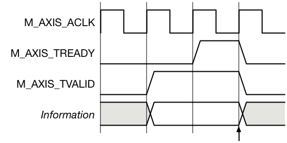
TVALID before TREADY handshake
In the timing diagram to the right, the master presents the transfer information and TVALID. TVALID must remain active until the slave drive’s TREADY. The transfer occurs when both TVALID and TREADY are asserted at the rising edge of ACLK. This is shown with the arrow in the timing diagram.
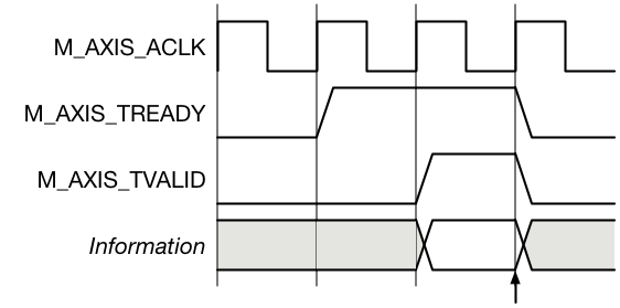
TREADY before TVALID handshake
In the case shown to the right, the slave presents TREADY and then subsequently the master asserts TVALID. The transfer occurs when both signals are asserted and ACLK rises. This is again shown with the arrow.
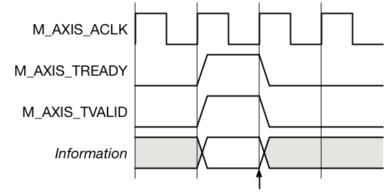
TVALID with TREADY handshake
In the timing diagram to the right, the master asserts TVALID in the same cycle that the slave asserts TREADY. The transfer occurs that cycle as indicated by the arrow.
Signalling
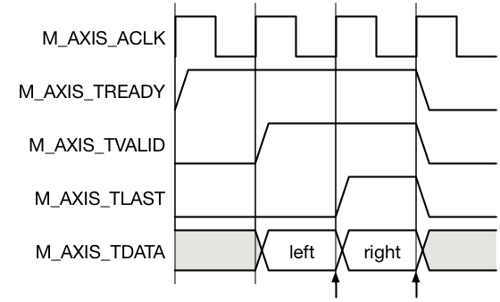
I2S audio packet transfer
In our case, we only need to send the 32 bits of audio data on TDATA and indicate the end of the packet with TLAST. On the first transfer cycle, we’ll send the left channel data with TLAST low, and then on the second transfer we will send the right channel data with TLAST high. Our application will not need any of the optional AXI4 Streaming signals.
Naming
In Vivado, we’re going to want to use a naming convention which allows the IP Packager tool to recognize the signals in the AXI4 Streaming interface. To do this, we’ll prefix all of our port names in the interface with M_AXIS_. Here is a list of the signal names we need to use:
| Signal | Direction | Description |
|---|---|---|
| M_AXIS_ACLK | Input | This is the clock signal for the module. It is driven in to both the master and the slave. |
| M_AXIS_ARESETN | Input | When this signal is low you should reset the M_AXIS_TVALID signal so that you don't indicate you have valid data to drive. |
| M_AXIS_TVALID | Output | Indicates that you have valid data to transfer to the slave. |
| M_AXIS_TREADY | Input | Indicates the slave is ready to receive your transfer. |
| M_AXIS_TDATA | Output | The data being transferred. |
| M_AXIS_TLAST | Output | Indicates that this transfer is the last transfer in the packet. There are two transfers per packet. The first is the left data and the last is the right data. |
Logic
You will need to add logic to generate M_AXIS_TVALID. This will need to get set when data is available to transfer to the AXI4 Streaming interface. It will need to clear when the data is read by the AXI4 slave, as indicated by M_AXIS_TREADY. Also, you will need to reset this to zero when M_AXIS_ARESETN is low.
You’re going to need to provide some type of selection logic which drives the left or right channel data onto the M_AXIS_TDATA output, depending on which channel we are sending.
Finally, you’ll also need to make a M_AXIS_TLAST output which indicates that the right channel is being read.
Test
The test is much like the previous parts for this tutorial, but it also adds a Bus Functional Model for the AXI4 slave interface. This model will accept the data transferred by your I2S receiver interface. It also uses a Queue model to hold expected data values. Those files along with the test are linked here:
The test will send I2S transactions to your design and receive AXI4 transactions from it. It will check that the received left and right data match, and that each packet has eight bytes of data. There can be issues in synchronizing your design with the test. If this happens, the test may report a large number of errors, but in fact there is just an alignment issue in that your logic generated extra initial AXI4 packets with uninitialized data. When you get errors, look at the first errors and see what the problem might be. Are the outputs shifted in time from the expected outputs? Are the left and right channels swapped? Are the left and right samples paired with the wrong packet? These could all be errors.
The test will not try to read a packet from your design until it has completed sending an I2S sample. It’s legal for your design to assert that it has valid data, even though it doesn’t initially. It’ll still work just as long as by the time the first I2S sample (both left and right) are sent, your logic has valid data.
Hints
At first blush, this design seems more complicated than it really is. If you find yourself adding lots of logic you are probably going down the wrong path. The simplest thing to do is get rid of the data_left and data_right registers and just replace them with a M_AXIS_TDATA register. This will hold left and right samples alternating in time. Then you just need an always block to create the M_AXIS_TVALID output and another to create the M_AXIS_TLAST output.
Hi Pete,
Looks like a permission change has occurred for:
common_test_util.v
queue.v
The server http://www.beyond-circuits.com:80 requires a username and password. Server says authorization realm.
Eric
Sorry about that. I am using a new system where the files I link to are in my subversion repository. I needed to add public read access to the testbench area. Try it again and let me know if it doesn’t work.
-Pete
Hi,
Can you please provide the axi logic code as I am a bit confused :
Regarding how to set M_AXIS_TVALID and M_AXIS_LAST. Can you please explain this in more detail on how to set these.
Please note that i am new to FPGA.
You set M_AXIS_TVALID when you have put the valid data on M_AXIS_TDATA. This indicates to the slave that you have data to send it. In our case one audio sample takes to data words. One for left and one for right. We send the left first and the right second (or last). So for the left sample you set M_AXIS_TLAST low. Then for the right sample you set it high. Remember that you need to set M_AXIS_TVALID low again once the slave has indicated that it has read the data by sending you M_AXIS_TREADY. You can look at my completed i2s_receive design here http://www.beyond-circuits.com/repos/tutorial/trunk/rtl/i2s_receive.v
Let me know if you still have questions or can’t get it to work.
Hi Pete,
kindly can you upload “common_util.vh” as it’s required by queue.v
Sorry about that. I added a link. Let me know if there is still a problem.
-Pete
Hi, I need to have axi streaming interface ( tx and rx) wothout dma to fpga . how to create driver in Linux for axi streaming.
Easy question to ask. More difficult to answer.
If I were to do this I would make a “user mode” driver. You can use the AXI streaming FIFO IP for this. It has an AXI streaming interface on one end and an AXI memory mapped interface on the other. The next question is how do you notify the software that there is data available. That can be as simple as polling the status of the FIFO. If there is data then read it. In that case you don’t even need a driver. But one core will constantly be running to poll the FIFO. The alternative is to use an interrupt. This gets more difficult though. For this you will need some kernel level code to handle the interrupt. I have done this using a file descriptor. The user mode code reads from the descriptor and blocks. When the interrupt occurs the kernel driver writes a byte to the descriptor. Then the user mode code can read the data directly from the FIFO.
I don’t have any recommendations on where to look for this type of code though. There should be something out there. Let me know if you find a good resource for this. It would probably make a good tutorial.
-Pete
Hi Pete: When you say in the post that “we only need to send the 32 bits of audio data on TDATA and indicate the end of the packet with TLAST”, do you mean that the left data word and right data word are 16-bit (total 32)? Or do we handle 64-bits (two 32-bit words for left and right) with the data packet.
Andy, we are handling two 32-bit audio values. So 64 bits total. Let me know if you need more clarification.
-Pete
Yes that makes sense, and it is what I understood from following the previous blogs. The part I’m trying to understand now is how I can “exit” the AXI streaming model without generating errors. For example, let’s say that I want to use a multiplier on one of the two channels. I think I can take the AXI streaming interconnect block and set it up as 1 slave on input (to receive two data words, left and right, from the I2S AXI master), and two masters on output (to separate left and right channels?). The multiplier IP block is not in AXI format. Can I just take the tdata[31:0] from the one of the interconnect masters, and interface to the multiplier, and ignore all the other AXI signals?
Just create your own IP block in Verilog or VHDL like I show in the tutorial. Then code the multiply in the RTL. You can make it do whatever you want. Add some registers you can control with the ARM to set gain values and then multiply the sample values from the AXI stream.
Hi Pete
I wrote my i2s receiver code as a series of states. In my implementation, I don’t set M_AXIS_TLAST or M_AXIS_TDATA until I have collected the left and right samples. When I run the simulation, it appears to work (at least the data is captured at the rising edge of sck). However, as configured, the test bench only captures two sd values. I need to run through 64 sck cycles (capture the full left and right sample) before I set M_AXIS_TLAST and M_AXIS_TDATA. Where can I make a change in the test bench that allows for more cycles to run to see if my code really does this correctly?
Regards
Andy
Okay I figured out how to extend the simulation time (just a setting in the toolbar!). I’m expecting ws to be high for 32 sck cycles followed by low for 32 sck cycles. I’m not getting that behavior in the simulation of my design against the test bench. I’m also not seeing it in the simulation of your design (the one posted above in the comments). Probably something wrong on my end — let me know if you have any thoughts on where to look.
I’m still having trouble passing this lesson. In my design, M_AXIS_TDATA is always zero except as follows — when the falling edge of the frame clock is detected, one more data bit is collected for the right audio sample at the rising edge of SCK. At the next positive edge of M_AXIS_ACLK, M_AXIS_TVALID is set, and the left audio sample is sent as M_AXIS_TDATA (if M_AXIS_TREADY), and at the next positive edge of M_AXIS_ACLK, the right audio sample is set as M_AXIS_TDATA, and M_AXIS_TLAST is set (if M_AXIS_TREADY)_. At the next M_AXIS_ACLK, M_AXIS_TDATA, M_AXIS_TLAST, and M_AXIS_TVALID go to zero, and the next left audio sample starts to be collected. My code will respond to arbitrary transitions of the frame clock, but M_AXIS_TDATA will be all zeros except for the data bits collected since the last transition of the frame clock. I’m wondering if the test bench will work with my code, given that the test bench appears to not reset M_AXIS_TDATA, and it does not necessary collect DATA_WIDTH bits between frame clock fall edges.
Andy, sorry to take so long to respond. Would it be possible to send me your code? It’s hard to say what the issue could be without it. You can email it to me or share it in some other way. You might be able to post it in a comment. I’m not sure that will work though.
Thanks,
-Pete
Hi Pete. The forum doesn’t seem to accept attachments. What email can I use?
Just send it to pete at this domain name.
Hi Pete
First of all, thanks for the great tutorial; I’m really learning a lot. Also I appreciate your willingness to look at my code and to provide feedback. I attached “i2s_rx.v”, and “i2s_rx.txt”. They are the same file – I just wasn’t sure which would be easiest for you.
A few comments that I think may help to look at the code:
A small detail: I prefer bclk, lrclk, and sdata instead of sck, ws, and sd.
The code starts using lesson 18.3 technique to find the rising and falling edge of bclk and lrclk.
Lrclk is registered, because I use that to determine whether I am collecting the left word or the right word.
I then use 6 states to implement the receiver:
1. RESET – this just resets the timing of the receiver. It looks for the next falling edge of lrclk, and then transitions to the next state
2.FIRST_BIT – this just looks for the first rising edge of bclk after RESET (i.e. after we saw the falling edge of lrclk). It doesn’t do anything else, since the associated sdata bit of this bclk rising edge is actually the LSB of the previous word. Basically I throw this bit away, and transition to the next state.
3.COLLECT_LEFT — on rising edge of bclk and the lrclk_reg not true, collect sdata bit in the left word. If lrclk_reg changes to true, then get one more sdata bit for the left word and transition state
4.COLLECT_RIGHT — on rising edge of bclk and the lrclk_reg is true, collect sdata bit in the right word. If lrclk_reg changes to false, then get one more sdata bit for the right word and transition state
5.SEND_LEFT – when the downstream slave indicates TREADY, send the left word with TLAST not true, and transition state
6.SEND_RIGHT – when the downstream slave indicates TREADY, send the right work with TLAST set to true, and transition state to COLLECT_LEFT
If the downstream slave is ready, this code should send both words in 2 ACLK cycles after getting the last bit in the right frame, and complete this well before the next rising edge of bclk (the start of the next left word).
I do not expect to get the first word correct on the test bench. This is because the test bench has lrclk go low immediate after ARESETN goes high. You can see that my code will take a few ACLK cycles to synchronize to the first falling lrclk edge that it sees, so I think I miss this first word. [actually I probably miss both the first left and right words] But I expect after this one to always capture the words correctly.
In fact, I do correctly receive some words, but I get most of them wrong. When I do get a word right, I checked the test bench, and in those cases, there are 32 bclk transitions in the frame. However many of the lrclk transitions do not contain 32 bclk transitions – there are fewer. In this case, since I shift each new sdata bit into LSB position of the left register or right register, if the lrclk edge comes early, the first bit will not be in the correct position when I send the words.
Am I right about why my code fails the test bench?
And, should the test bench fail my code? My opinion is that if there are fewer bclk cycles than 32 in the frame, the transmitter has made an error, and it is not an error in my code. My code will behave correctly if there are 32 bclk cycles in each frame.
What do you say? And thank you very much!
Regards
Andy
Andy,
The I2S receiver doesn’t know how many bits the transmitter will send. It could be one or a hundred. The standard says that the most significant bit is transmitted first. You are shifting this into a 32-bit shift register. The problem is that if you don’t get exactly 32 bits your most significant bit won’t line up in bit 31 of your AXI output stream. Part 2 of the tutorial 18 discuses this. And if you look at the example schematic there you can see that it is not actually using a shift register at all.
Since the receiver doesn’t know how many bits the transmitter will transmit, the test actually changes this number on the fly. A normal I2S transmitter will probably never work this way. But according to the standard it can if it wants to. And a proper receiver should still do the right thing. The purpose of a test after all is to stress the design.
Let me know if you still have questions or trouble getting it to work.
-Pete
Thanks Pete — yes I didn’t understand that detail correctly. I understood that the transmitter might send a different number of bits, but that this number was constant and known in advance for any particular transmitter. So I thought a simple parameter for the number of bits would be sufficient. I’ll see how I do trying to add the flexibility to handle a varying number of bits.
Hi Pete,
You’re a life saver, finding your tutorials very informative.
Currently having an issue accessing common_test_util.v file
Its asking for username and password.
Hello
I am not able to access the code
Will u pls help me
Hi Pete,
When I try to access common_util.vh it asks for a username and password
Should be fixed. Please try now.