In this tutorial, let’s have a little fun. Now that we can receive audio data and send it back out, we might as well do something with it. In this tutorial, we’re going to make a speech jammer.
What’s a speech jammer? We’re going to take audio input from a microphone and delay it about 450 milliseconds and then play it back out. Most people find it really difficult to talk with the delayed audio feedback. Curiously, it doesn’t seem to affect me much. I think people that know me might not find that so strange. Here’s a lovely reading of Dr. Seuss’ book One Fish Two Fish.
Overview
To get something basic working, all we need is a module which receives the AXI4 audio stream and delays it, which then produces an AXI4 audio stream out. The block design looks something like this:
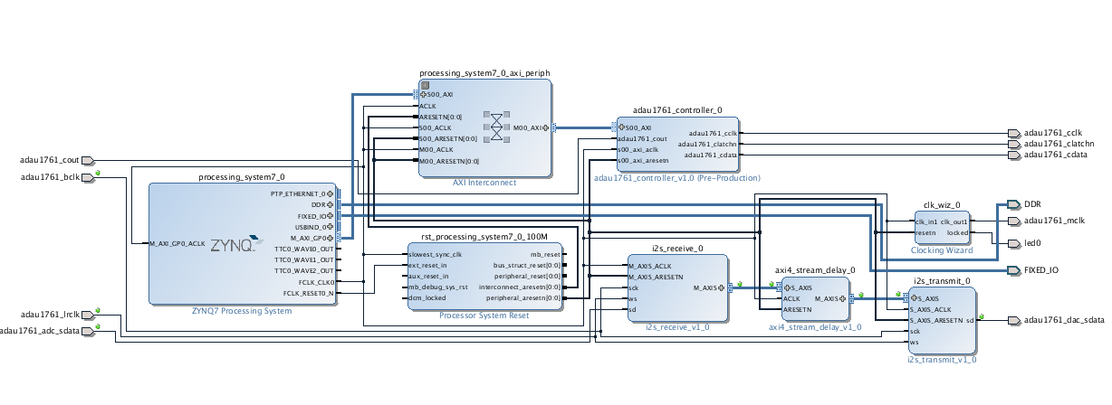
All we do is insert the axi4_stream_delay module between the I2S receiver and I2S transmitter. There’s only one gotcha: the axi4_stream_delay module doesn’t exist, and we need to write it.
The AXI4 stream delay module
The axi4_stream_delay module accepts audio data on an AXI4 streaming slave interface, stores it in a buffer, and then sends it out an AXI4 streaming master interface. To keep things simple, our module will make a few assumptions. The first is that it is receiving audio data so that the packet size is 8 bytes. The second is that we don’t need to keep all the bits in the audio data, we may want to truncate some of the data to save on memory requirements. The third thing is that the maximum delay is fixed as a parameter to the module, but there is a delay input which is able to specify how many samples we want to delay. Your module declaration should look something like this. We’ll also be including a scale input that specifies a scaling value so we can turn up the volume on the audio as it passes though the block.
module axi4_stream_delay #
(
parameter DATA_WIDTH = 32,
parameter SAMPLE_WIDTH = 16,
parameter MAX_DELAY = 8192
)
(
input ACLK,
input ARESETN,
input [$clog2(MAX_DELAY)-1:0] delay,
input [$clog2(SAMPLE_WIDTH)-1:0] scale,
input M_AXIS_TREADY,
output reg M_AXIS_TVALID,
output reg M_AXIS_TLAST,
output reg [DATA_WIDTH-1:0] M_AXIS_TDATA,

output reg S_AXIS_TREADY,
input S_AXIS_TVALID,
input S_AXIS_TLAST,
input [DATA_WIDTH-1:0] S_AXIS_TDATA
);
The DATA_WIDTH parameter specifies the width of the TDATA bus. The SAMPLE_WIDTH parameter specifies the amount of audio data we want to store for each sample. So the module is going to only store bits DATA_WIDTH-1 through DATA_WIDTH–SAMPLE_WIDTH in the buffer. The lower bits will be thrown away. Memory space within the FPGA is pretty precious, so it’s a good idea to not waste it. The final parameter MAX_DEPTH specifies the maximum amount of delay. To calculate the time of the delay, recall that our audio data is arriving at 48kHz, or one sample every 20.833µs. The default value of 8192 will produce a maximum delay of 171ms.
The buffer
Flip-flops in an FPGA are extremely flexible. They can be updated at pretty much any time, and their outputs can be used whenever you want by as many consumers as you want. This flexibility comes at a high price, though, in terms of area and power. Sometimes you have a need to store a lot of information and this information doesn’t need to be accessed all the time like a flip-flop. The FPGA contains a large number of small RAM memories. These are much denser than the flip-flops and use much less power. There are limitations about how you can access them, though.
To use a memory in Verilog, you need to declare a reg array. The array will have a width and a depth. Here’s the declaration for the memory in our module:
reg [2*SAMPLE_WIDTH-1:0] delay_mem[MAX_DELAY-1:0];
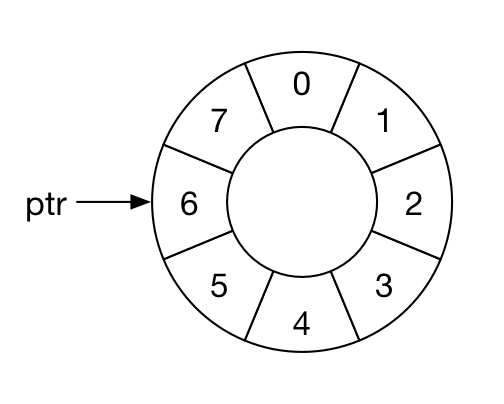
A circular buffer
Each element of the array can hold two samples. The array has MAX_DELAY elements indexed between 0 and MAX_DELAY-1.
In order to use the buffer, we need a pointer which indicates the address that we want to write to and read from in the buffer.
Here is a declaration for the pointer:
reg [$clog2(MAX_DELAY)-1:0] ptr;
We want our buffer to be circular. That just means that when the pointer has the value of delay-1 and we increment it, it just wraps back to zero. Here is the code to manage ptr:
  always @(posedge ACLK)
    if (!ARESETN)
      ptr <= 0;
    else if (buffer enable condition)
      if (ptr+1 == delay)
	ptr <= 0;
      else
	ptr <= ptr+1;
When you code a flip-flop, you are using a Verilog construct which the synthesis tool recognizes as a template for a flip-flop. Likewise, you need to code a memory using a proper memory template which the synthesis tool can then recognize. Also, the memories inside the FPGA are synchronous, which means they need to use a clock signal. If you have used SRAM parts before that were asynchronous, these may be a little different. The code below assumes the value being written to the RAM is called in_reg and the value being read from the RAM is stored in out_reg.
  always @(posedge ACLK)
    if (!S_AXIS_TREADY && !M_AXIS_TVALID)
      begin
	delay_mem[ptr] <= in_reg;
	out_reg <= delay_mem[ptr];
      end
There are a number of different templates for RAMs depending on what type of RAM you want the tool to use. The RAMs used in the FPGA are dual port. Each port can have its own clock, address, write port and read port. For more information on inferring RAMs in your design, consult the Xilinx Answer Record 46515.
Tasks
I have given you the code that reads and writes the circular buffer and the module declaration. You need to provide code which implements an AXI4 slave interface which stores the left and right sample data in in_reg, code which takes data in out_reg and writes it out the AXI4 streaming master interface, and code which decides when to write and read from the memory.
Since we read and write to the RAM at the same time, the slave and master interfaces need to be synchronized. You enable the RAM when the slave input buffer in_reg has valid data in it, and the master interface has sent the data it had in out_reg.
When you transfer the data from out_reg to M_AXIS_TDATA you need to align the value such that the MSB of M_AXIS_TDATA is lined up with the MSB of out_reg. You will need to shift the out_reg value left by DATA_WIDTH–SAMPLE_WIDTH. We also want to scale the data by the value specified by the scale input. To do that, just shift left by DATA_WIDTH–SAMPLE_WIDTH+scale.
Test
A test axi4_stream_delay_test.v is attached, which can be used to verify your design. This test makes use of the common_test_util and queue modules found in the other tutorials, as well as the AXI4 stream master and slave bus functional models.
Note that the test does not vary the depth or scale inputs during the test. It is possible to modify those parameters for the test, but in this case, they remain static throughout.
Building the FPGA
Now build your FPGA using a block design like the one shown above. You should modify the delay parameter on the AXI4 stream delay module to 16384. That gives us about 342ms of delay.
Software
We have to make some changes to the software that initializes the ADAU1761 audio chip. In previous tutorials, we just wanted to receive audio from the line in and send it out to the headphones. In this tutorial, we’ll need to take audio data from the microphone input. Also, I found it helpful to increase the gain on the audio, so we’re going to do that as well.
The changes are that we increase the input gain on the left and write channels. The mixer control registers are at address 0x400a and 0x400c. We write a value of 0xf there to un-mute the microphone input and increase the input gain to 6dB. We also set the left and right mixer gain (0x400b, 0x400d) to 6dB (0x7). Finally we need to turn on the mic bias by setting register 0x4010 to 0x5. Use main.c in your SDK project for this tutorial.
Using the speech jammer
Now you just need to find some headphones and a microphone. You want to minimize the sound that a person hears directly when they speak, so over-ear headphones work the best. Alternately, you can use ear buds and then over-ear hearing protectors. This is actually the best setup. You’re also going to need a mic. It is important that the mic gain be very high, and you’re really going to want to speak directly into the mic.
It can also be helpful to increase the gain of the audio signal so that the speech is louder in the ear of the speaker. You can do that in the axi4_stream_delay module by scaling the data as it passes through. I found that a factor of eight worked best for my mic and headphones.
Now try it out on your friends, and see what happens.
Hi Mr.Johnson,
Thanks for the tutorials.
I implemented the above tutorial and it works .
Now I am trying to write the data out of i2s_receive to the Memory of Zynq PS through DMA Controller and then read it once certain audio samples have been written.By this I can loop the audio when ever desired .
I am not able to properly write the data to the memory through DMA because the interrupt from the DMA does not generate properly always which I believe depends on the TLAST Signal .
Do you have any suggestions or where I might be going wrong ?
Can you please guide me on this ?
Thanks Again,
David
I’m glad you got the basic tutorial working. I haven’t implemented DMA yet. I’m on vacation this month so I won’t be able to offer any help. DMA is on my target list for a future tutorial.
Thanks for the reply .
Happy Vacations 🙂
David
Hi pete,
I am using zynq zc702 fpga board.I have to generate a continous data stream from my PL side and put into PS.so how to do this please suggest me.
Thanks
Deepak,
You would use an AXI streaming interface to connect to a DMA controller. The DMA controller will buffer the data and then send it into the PS memory using AXI memory cycles. I plan on covering that when I continue the audio tutorials.
Hi Pete,
I finally reached tutorial 21, and it is going well. But I cannot understand what you wrote in the tutorial as following:
When you transfer the data from out_reg to M_AXIS_TDATA you need to align the value such that the MSB of M_AXIS_TDATA is lined up with the MSB of out_reg. You will need to shift the out_reg value left by DATA_WIDTH–SAMPLE_WIDTH. We also want to scale the data by the value specified by the scale input. To do that, just shift left by DATA_WIDTH–SAMPLE_WIDTH+scale.
DATA_WIDTH=32, SAMPLE_WIDTH=16 and scale>0. we will left-shift the out_reg by DATA_WIDTH–SAMPLE_WIDTH+scale, and then put out_reg to M_AXIS_TDATA. We only truncate some parts of out_reg, the length of which is SAMPLE_WIDTH. Presumably,
scale=8. DATA_WIDTH–SAMPLE_WIDTH+scale=24. Hence, we will left-shift the truncated out_reg(SAMPLE_WIDTH=16) by 24 bits, and then the length of the out_reg will exceed the length of M_AXIS_TDATA. That makes me very confused, could you please explain it a bit more? Why does this kind of left-shift works? and Why does turn up the volume?
Regards
Alex
Hi Pete,
Can I see your axi4_stream_delay module?
Thanks,
Roopa
You can download the file here https://www.beyond-circuits.com/repos/tutorial/trunk/rtl/axi4_stream_delay.v
Let me know if that doesn’t work for you.
Hi Pete,
I would like to thank you again for great tutorials and, if you don’t mind, do some self-advertising here. I’ve completed your tutorials and the results of that are now available on [1]GitHub.
@Alex
This explanation might be coming a bit late but the reason why the left-shift works is as follows.
The samples you are getting from/sending to ADAU1761 are plain result of PCM. The ADAU1761 uses numeric format 5.23 for internal processing but it’s serial port sends/accepts only 24 bit values (hence, the format “on the wire” is 5.19) with the MSB being the sign bit (S). So if the sample represents a positive value (S=0) it is most likely that the bits to the right of S are also 0s and 1s appear further to the right. Shifting such a value shouldn’t cause problems as long as some 1 doesn’t reach the position of the sign bit. OTOH, if S=1 (meaning, the sample represents a negative value, and we know that the negative values are 2 complements) then most likely the bits to the right of S are also 1s. Hence again, as long as some 0 doesn’t reach the position of the sign bit all should work. And notice that in either case (positive and negative values) shifting left means multiplying by 2 the ‘before-shifting-value’ so you are getting louder audio.
Hope some of that makes sense,
Cheers,
Zdzislaw
[1] https://github.com/zdzislaw-s/audio-processing
I just realised that there is a bit of misinformation in my comment above. The [1]documentation for ADAU1761, in the Figure 68, page 46, shows that the chip’s DATA IN/OUT format is 1.23 (and not as I stated 5.19). This shouldn’t bare much of significance for the rest of my explanation though, I hope.
[1] http://www.analog.com/media/en/technical-documentation/data-sheets/ADAU1761.pdf
Zdzislaw,
I’m glad to see that the tutorials were so helpful for you. My intent with them was to provide guidance but not just do everything. That way you promote understanding by trying, failing, and figuring it out. It looks like you really understood that. Thanks for making your results available to others too.
-Pete
Pete,
There are quite a few places that tell you how to start developing for Zynq but most of the time they do that in such a way that it doesn’t exercise your brain cells 😉
Your tutorials are different – which is the reason why I value them so much. I don’t think I can thank you enough.
Zdzislaw
Hi Pete,
THanks for your wonderful tutorial.
With the mic input configurarion in the above main.c, the board is working fine using line input, but not working using mic as input.
Could you please suggest me how to debug ?
@Zdzislaw
Thanks for your github. But it seems you only use the line input, not mic input, right?
All I can suggest is to make sure that the register values are being written correctly in the CODEC. It has been a long time since I have worked on this so I don’t recall what debugging steps I might have taken.
-Pete
Hey,
I found your tutorials very helpful, but I am trying to produce sound by sending digital signals to the audio codec and tranform them into analog signals, aka drum-like sound played on speakers. Any tips?
Victor,
I’m not really sure how you should go about doing that. Maybe sample some sounds that you want to reproduce. You could store those in RAM and stream them out when you want. Or you could figure out how to algorithmically reproduce the sounds.
Sorry that I don’t have more experience with audio.
-Pete
HI Pete, Have you implemented DMA to store samples from I2S RX and from DMA to I2S TX?
No, I haven’t implemented the DMA portion. If someone gets that working I’d be happy to post it. It’s been quite a while since I have had time to work on these tutorials.