
In my current project we are using a PicoZed module with a custom carrier board. But the carrier board does not have a SD card so we want to boot Linux from the eMMC module on the PicoZed board.
There is a good document from Avnet about it but there are a couple of things you need to know to get it working. I thought I would cover what I needed to do to get it working here.
Overview
First I want to go over a high level description of what we are going to do. It can be a little confusing. Normally on the FMC development board you boot the board using the SD card. You program a BOOT.BIN and an image.ub onto a FAT filesystem on the SD card, plug it in to the carrier board, and boot. You can program the SD card on your build machine or as I usually do once development is in progress I just scp the files from the build machine to the development board directly. That way you don’t need to move the SD card physically.
Without an SD card in your carrier board things change a little. The goal is to not boot the board using the QSPI interface to a Micron FLASH chip. This only loads UBoot. UBoot then programs the FPGA and then uses the SD card interface to access the eMMC chip on the PicoZed. This eMMC chip behaves like an SD card but is not removable.
So to get all this working you first need a Linux build and FPGA which can access both the SD card on the PicoZed FMC carrier board, and the eMMC on the PicoZed module. Next you need to build your target FPGA application which accesses the eMMC memory and the Linux build for your application.
We will use this bootstrap Linux build and FPGA to write our actual application FPGA and Linux build to the QSPI FLASH and eMMC memory. Then when we place our PicoZed module in our application carrier board it will boot our target application. If you included Ethernet on your carrier board then you can use that to update your eMMC as your development progresses. If you didn’t include SD support or Ethernet (what were you thinking?) on your carrier, then you need to use JTAG to program your images or you need to keep moving PicoZed modules back and forth between your carrier board and the FMC carrier board.
Bootstrap FPGA Requirements
Enable the second SDHC controller
Connect the chip detect to a logic zero
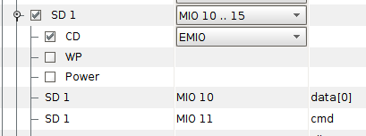
First, on your bootstrap FPGA design you need to enable the SD 1 device in the MIO configuration for the ARM processor. Use MIO pins 10 through 15. Also, you need to enable the Chip Detect port (CD) and connect it to EMIO. You will need to connect this to a logic zero in your FPGA design.
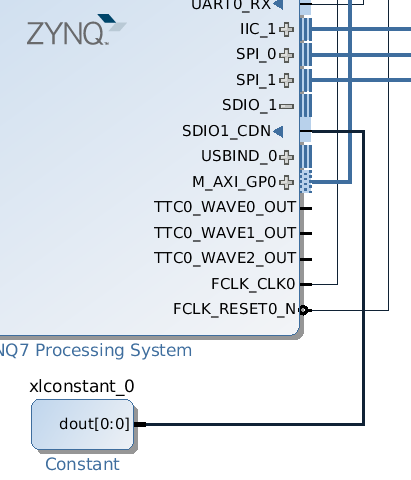
Once you have done this you can build your FPGA and export the hardware description to SDK. My FPGA has just the ZYNQ processor, the constant 0 feeding to the SDIO1_CDN pin and the FCLK_CLK0 feeding back to the M_AXI_GP0_ACLK input of the ZYNQ module.
Configure Linux
Use petalinux-config with the –get-hw-description to pull in the hardware for the FPGA to Linux. If you used an older version of the PicoZed BSP you will need to modify the subsystems/linux/configs/device-tree/system-top.dts file and add the following lines. The default compatible value for the FLASH chip is not specific enough to enable the eMMC chip on the PicoZed. Check the file to see if you need to make the changes. You should see an entry like this.
&qspi {
  flash0: flash@0 {
    compatible = "micron,n25q128a13";
  };
};
Bootstrapping
You should now run petalinux-build and petalinux-package to build a Linux that will boot from the SD card on a carrier board. This build will be aware of the eMMC chip and be able to control it. The plan is to boot this Linux from an SD card with the PicoZed plugged into an FMC carrier board which does support SD cards. We will then copy the image we build in the next steps onto the QSPI FLASH and the eMMC chip using this build. We can then remove the module and change the boot switch settings and have a module which will boot from QSPI and eMMC.
So copy the BOOT.BIN and image.ub files you build in the previous section to an SD card. Verify that this image boots in a FMC carrier. The critical component is that this image can read and write the QSPI chip. To verify that log in to the console and type
root@linux:~# cat /proc/mtd
ev:    size   erasesize  name
mtd0: 00500000 00010000 "boot"
mtd1: 00020000 00010000 "bootenv"
mtd2: 00a80000 00010000 "kernel"
mtd3: 00060000 00010000 "spare"
You should see the four partitions on the QSPI FLASH memory. You should also check that you can see the eMMC device file.
root@pz-7015-2016-2:~# ls /dev/mmcblk?
/dev/mmcblk0       /dev/mmcblk1
We need to partition the eMMC memory and write a FAT 32 filesystem onto it. Run fdisk like this
root@pz-7015-2016-2:~# fdisk /dev/mmcblk1
Device contains neither a valid DOS partition table, nor Sun, SGI, OSF or GPT disklabel
Building a new DOS disklabel. Changes will remain in memory only,
until you decide to write them. After that the previous content
won't be recoverable.


The number of cylinders for this disk is set to 115456.
There is nothing wrong with that, but this is larger than 1024,
and could in certain setups cause problems with:
1) software that runs at boot time (e.g., old versions of LILO)
2) booting and partitioning software from other OSs
   (e.g., DOS FDISK, OS/2 FDISK)

Command (m for help):
Type “p” to print the partition table.
Command (m for help): p

Disk /dev/mmcblk1: 3783 MB, 3783262208 bytes
4 heads, 16 sectors/track, 115456 cylinders
Units = cylinders of 64 * 512 = 32768 bytes

        Device Boot      Start         End      Blocks  Id System

Command (m for help):
If you do have partitions you should delete them by entering “d” unless you know they are the correct size.
Next you should create a partition starting at 1 that is 128MB in size.
Command (m for help): p

Disk /dev/mmcblk1: 3783 MB, 3783262208 bytes
4 heads, 16 sectors/track, 115456 cylinders
Units = cylinders of 64 * 512 = 32768 bytes

        Device Boot      Start         End      Blocks  Id System

Command (m for help): n
Command action
   e   extended
   p   primary partition (1-4)
p
Partition number (1-4): 1
First cylinder (1-115456, default 1): 1
Last cylinder or +size or +sizeM or +sizeK (1-115456, default 115456): +128M

Command (m for help):
If you now print the partition table you should see the following
Command (m for help): p

Disk /dev/mmcblk1: 3783 MB, 3783262208 bytes
4 heads, 16 sectors/track, 115456 cylinders
Units = cylinders of 64 * 512 = 32768 bytes

        Device Boot      Start         End      Blocks  Id System
/dev/mmcblk1p1               1        3907      125016  83 Linux

Command (m for help):
Now write the partition table.
Command (m for help): w
The partition table has been altered.
Calling ioctl() to re-read partition table
root@pz-7015-2016-2:~#
Next we need to put a FAT 32 filesystem onto the partition.
root@pz-7015-2016-2:~# mkdosfs -F 32 /dev/mmcblk1p1
Now we need to build our application FPGA and Linux build.
Application FPGA
Configure your FPGA such that the SD interface uses MIO pins 10 through 15. If you have two SD card interfaces then you will need to configure UBoot to use the correct interface. Since you don’t have an SD card you only need one SD interface to talk to the eMMC chip so I recommend only using the one. As before, make sure that you enable the chip detect (CD) pin and connect it to a logic 0.
Application Linux
Now you need to configure the Linux build for your application. Create your project and run petalinux-config with the –get-hw-description option to read the FPGA settings. When the menuconfig screen comes up you need to set the boot image location to QSPI. Go to
- Subsystem AUTO Hardware Settings ->
- Advanced bootable images storage Settings ->
- boot image settings ->
- image storage media ->
Change the device selection to primary flash and then exit to move up one level. Set the kernel image location to eMMC. Go to
- kernel image settings ->
and set the device selection to primary sd. Then select exit twice to move up two levels. If you have two SD interfaces select
- SD/SDIO Settings ->
and change the device selection to ps7_sd_1. Now exit out of the configuration and build and package your linux. If you only had one SD card interface then this will be your only option.
Copy the application Linux build
Now, back on the PicoZed carrier board which has booted the bootstrap Linux from the SD card, copy the application Linux build files BOOT.BIN and image.ub to the SD card using ssh. Don’t overwrite the files you booted from but put the files in a separate directory. Instead of using ssh, you could plug the SD card into your development machine and transferring the files that way.
root@pz-7015-2016-2:~# cd /run/media/mmcblk0p1/
rroot@pz-7015-2016-2:/run/media/mmcblk0p1# mkdir application
root@pz-7015-2016-2:/run/media/mmcblk0p1# cd application
root@pz-7015-2016-2:/run/media/mmcblk0p1/application# scp user@build-server-ip:/project-path/images/linux/{BOOT.BIN,image.ub} .

Host 'build-server-ip' is not in the trusted hosts file.
(ecdsa-sha2-nistp256 fingerprint md5 ce:04:f3:db:96:67:d7:7a:6a:24:48:7e:a8:98:66:5f)
Do you want to continue connecting? (y/n) y
user@build-server-ip's password:
BOOT.BIN                                                                                                                                 100% 3889KB   3.8MB/s   00:00
user@build-server-ip's password:
image.ub                                                                                                                                 100% 6185KB   6.0MB/s   00:01
root@pz-7015-2016-2:/run/media/mmcblk0p1/application# ls
BOOT.BIN  image.ub
root@pz-7015-2016-2:/run/media/mmcblk0p1/application#
Verify that you can see the QSPI partitions.
root@pz-7015-2016-2:/run/media/mmcblk0p1/application# cat /proc/mtd
dev:    size   erasesize  name
mtd0: 00620000 00010000 "boot"
mtd1: 00020000 00010000 "bootenv"
mtd2: 00960000 00010000 "kernel"
mtd3: 00060000 00010000 "spare"
Now copy the BOOT.BIN to the QSPI partition 0 using the flashcp command.
root@pz-7015-2016-2:/run/media/mmcblk0p1/application# flashcp BOOT.BIN /dev/mtd0
Next mount the eMMC partition and copy the linux filesystem to the eMMC.
root@pz-7015-2016-2:/run/media/mmcblk0p1/application# mount /dev/mmcblk1p1 /mnt
root@pz-7015-2016-2:/run/media/mmcblk0p1/application# cp image.ub /mnt
The system is now ready to boot from QSPI and eMMC. With the board oriented such that SW1 is at the bottom, set the switches such that the switch on the left is pushed towards the edge of the board and the one on the right is pushed towards the center. Now remove the SD card and reboot the board.
Conclusion
Your board should now boot without the SD card. If your board fails to boot, check the SW1 settings. If they are not correct, the boot loaded will fail to load and the FPGA will not be programmed. If you see the bootloader load and program the FPGA but fail to find a Linux image to boot then it is likely configured to look for the image on the SD card rather than the eMMC. Make sure you have configured the correct SD device for boot, or simple use only the eMMC SD interface on your FPGA.
Hi Pete,
Thanks for the excellent tutorial! I have a similar situation – I’d like to boot Linux on my PicoZed, but I don’t have an FMC carrier card, and so cannot copy from SD to eMMC.
Is there a way to boot from QSPI and eMMC without going through the intermediate SD card steps you outlined above?
I can boot from JTAG, but that’s about it. Linux boots, and I can see the eMMC device (fdisk wirks fine) but the “mkfsdos” command doesn’t seem to be available to me (i.e. not in busybox), so I cant make a FAT 32 partition on my eMMC. Any suggestions or tips would be most welcome!
The solution is to boot using JTAG. I’m surprised that mkfsdos was not included in that Linux build. You may need to use petalinux-config and specify that it be included on the root filesystem. Sorry, I don’t have exact instructions.
-Pete
@Pete,
use the following command to format
mkfs.vfat -F 32 /dev/mmcblk0p1