
In this tutorial, we are going to cover a little bit more on simulation. In addition, we’ll discuss an important subject that causes some confusion.
Blocking Versus Non-Blocking Assignments
The very observant reader of the last tutorial might have noticed there is an ambiguity in what the simulator needs to be doing. In our FPGA, we had an assignment which set the value of the the led outputs to be the same as the switch inputs on the rising edge of clk. Here is the code:
always @(posedge clk) led = switch;In our test bench module, we drove the switch values to random values on the rising edge of clk as well.
always @(posedge clk) switch = $random;So the question is, which of these events happens first in the simulation? In real hardware, it is possible for them to happen simultaneously, but in the simulator this is not possible. So, which goes first? The answer is, quite simply, we don’t know. It’s unclear ahead of time which one will execute first. And which one is executed first has an impact on the simulation’s behavior. Even if it were possible to know, this situation is so common that making a working simulation with a real-life design would be just about impossible. You would be spending all of your time trying to keep track of which block goes before which other block. Furthermore, it is actually impossible because sometimes, two blocks might both need to go first. Consider the code below:
module top(input clk, output reg a, output reg b);
  initial a = 0;
  initial b = 1;
  always @(posedge clk) a = b;
  always @(posedge clk) b = a;
endmodule
When I simulate this a is set to 1 right away, and then nothing ever changes. a and b are both 1 for the entire simulation.
If you elaborate the RTL design and look at the schematic, you’ill see the correct implementation:
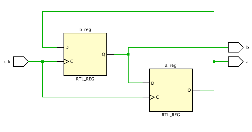
Synthesized design
The sequential assignments above are called blocking assignments. Verilog also supports a different assignment operator called a nonblocking assignment. The example below shows the same code with nonblocking assignments.
module top(input clk, output reg a, output reg b);
  initial a = 0;
  initial b = 1;
  always @(posedge clk) a <= b;
  always @(posedge clk) b <= a;
endmodule
When the simulator encounters a nonblocking assignment, it evaluates the right hand side of the expression and schedules that value to be assigned to the left hand side of the expression once all other always blocks are evaluated. It is critically important that you always use long blocking assignments when assigning to output values in sequential always blocks. Likewise, always use a blocking assignment when assigning the output of a combinational always block.
You should take the time now to modify your existing top.v and bench.v files to use the nonblocking assignment operator where appropriate.
Here is what I have for my top.v file
`timescale 1ns / 1ns
module top
 (
 input clk,
 input [7:0] switch,
 output reg [7:0] led
 );
 always @(posedge clk) led <= switch;
endmodule
And here is my bench.v file
`timescale 1ns / 1ns
module bench;
 reg clk = 1;
 always #5 clk = ~clk;

 reg [7:0] switch;
 wire [7:0] led;
 top top
 (
 .clk(clk),
 .switch(switch),
 .led(led)
 );

 always @(posedge clk)
 switch <= $random;

 initial
 begin
 repeat (1000) @(posedge clk);
 $finish;
 end

endmodule
Improving the Test Bench
The waveform below shows the last few clock cycles of my simulation. The switch and led values are random. However, notice how the led values lag behind the switch values by one clock cycle. This is to be expected, since the led values are captured in flip-flops on the rising edge of clk.
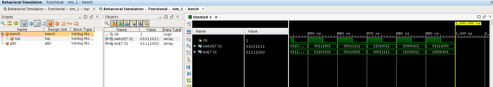
Simulation Waveform
We will now add a check to the test bench to compare the led outputs with an expected result. The first thing to do is to generate the expected result, which will be simply the switch variable delayed by one clock cycle.
  reg [7:0] expected_led;
  always @(posedge clk)
    expected_led <= switch;
Then, we will perform the comparison between the expected output and the actual output. We declare two integer variables called num_checks and num_errors and initialize them to zero. Integer variables are essentially signed 32-bit reg values. Then, on every clock edge, we perform a comparison. We’ll increment the number of checks counter for each time we perform this comparison, and increment the number of errors counter if the expected output does not match the actual output.
  integer num_checks = 0;
  integer num_errors = 0;
  always @(posedge clk)
    begin
      num_checks = num_checks+1;
      if (expected_led != led)
	begin
	  $display("ERROR: led value %0x does not match expected value %0x at time %0fns",
		   led,expected_led,$realtime);
	  num_errors = num_errors+1;
	end
    end
Finally, we modify the always block that stops our simulation so that it prints out a pass/fail message. I like to keep track of the number of comparisons so I can ensure that the fail message actually means something. It’s not a very good test if it passes with no errors and no comparisons. The message for passing and failing is distinctive and similar to allow scripts to check your simulation results. It’s a great feeling when you have the computer run hundreds of tests overnight, and then you come in the next morning to see all those passed messages. Automated regression testing is an important part of real-world FPGA engineering.
You should be able to make changes to your test bench and reproduce my results.
Synthesizable Verilog
As a final note, I should point out that there are different subsets of the Verilog language for different purposes. In these tutorials, we will discuss the Synthesizable RTL and behavioral subsets. We used lots of constructs in our test bench which have no place in an FPGA design proper. After all, what is your FPGA supposed to do if it encounters a $finish or $display statement?
In general, code which calls system tasks (those beginning with a dollar sign) are not synthesizable. Also, you can not use the #number construct to advance time in RTL code. Technically, strictly speaking you can use the #number construct in synthesizable code, but the synthesis tool will ignore it.
Hello Prof. Pete Johnson,
“Technically, strictly speaking you can use the #number construct in synthesizable code, but the simulator will ignore it.”
In bench.v, “always #5 clk = ~clk;” was wrote, and the simulator understood that, did not ignore “#number”. Please help me understand that!
Thank you!!!
I see the source of your confusion. The statement at the end of the tutorial was incorrect. The simulator will not ignore the delay, but the synthesis tool will. I have changed the text.
Be careful to not confuse RTL code with test code. To a simulator, the statement “always #5 clk = ~clk;” is perfectly reasonable. It means “schedule clk to be equal to its inverse in 5 time units, then repeat that again”. But what does it mean for the RTL code? How should a synthesis tool turn this into a schematic and map it into an FPGA? Maybe an inverter fed back on itself with a 5ns delay? But there is no way in the FPGA to create a precise ins delay. In general the synthesis tool will ignore any delays in the RTL code since it has no way to implement that function.
Thanks for the comment. Oh, and I’m not a professor.
Hello Pete Johnson a great coach/engineer if I may say,
Thank you!
I understood, probably, and going to Tutorial 4.
Hi Tran,
Just to add a point of information.
If you open the log file hopefully you will be able to see a message saying “the delay is ignored”. (Not exactly in the same words but similar to this). Whenever the synthesis tools does like ignoring delay or optimize something, it prints them in log file.
@ Professor Pete Johnson . I want to know what difference will blocked version and unblocked version have on Synthesis?
Thanks in advance
That is a tricky question. First make sure you understand the difference between blocking and non-blocking assigns for simulation. For synthesis, the synthesis tool tries to implement as closely as possible what the simulation semantics are. But there are some minor differences.
You first need to consider what happens on a combinational always block. The statement
always @(*) z = a&b;has no state. It is just an AND gate. If you change it to a non-blocking assign it would be incorrect for simulation, but synthesis would still implement just an AND gate. If you code a latch like thisalways @(*) if (g) q = d;then the synthesis tool will make a latch regardless of your use of blocking or non-blocking assignments. If you use a clocked always block to make a flip-flop like thisalways @(posedge clk) d < = q;then the synthesis tool will make a flip-flop regardless of your using a non-blocking or blocking assignment. The non-blocking assignment is (almost) always what you want in this case. But you can also use non-blocking and blocking assignments in the same always block. So if you sayalways @(posedge clk) begin z = a&b; q < = z; endthen the blocking assignment to z is combinational and produces just an AND gate and the non-blocking assignment to Q produces a flip-flop.Essentially, whether a flip-flop is produced depends on the visibility of the assigned variable outside the always block or within the always block on subsequent cycles. In other words, if the code relies on state being held then a flip-flop (or latch) will be produced. You need to be careful though. In the last example if the value for z is used in another always block then there will be two z values synthesized. One which is combinational that feeds into the flip-flop that produces q and another z value which is the output of a flip-flop - essentially the same as q.
Until you really get a good feel for the implications of all this you should really stick to using non-blocking assignments in always blocks sensitive to the edge of a clock to produce flip-flops or a combinational always block where you use a blocking assignment to assign to the always block outputs. It is critical in this case that you make an assignment for every path through the code. If you make it such that under some conditions an assignment is not made then you will generate a latch. So almost never want to make a latch structure.
I hope this helps. It is always good to work through some examples by writing some RTL code and then looking at the schematic that is produced when the code is synthesized.
Hi Pete Johnson,
I just want to know where is the $display print its output, because I cant the result in any of the window.
It should appear in one of the log panels at the bottom of the Vivado window.
Hi Pete Johnson, Thanks for a nice tutorial. I would like to ask whether mixing blocking and non-blocking assignments in one always block is a good habit. As far as I know, even though we could write two different assignments together inside a one synchronized block, putting all sequential logic to always (posedge clk) and all combinational logic to always (*) or using assignment statement is better way. I would like to know the reason why you’ve mentioned mixed assignment in one always block. Did you show it just to explore mixing assignments is possible?
I think that at times it can be cleaner to mix the blocking and non blocking assignments in one always block. I like to keep related code together. If you need something simple in a procedural block, like a for loop, then it can be better to place the code right next to the assignment. However, I think you should scope the intermediate variables that you make the blocking assignments to as local to the always block. That way there is never any chance of using the values outside the scope of the always block. In general I am never a big fan of “you should always code it this way” or “you should never do this”. There may be times when it is clearer and at any rate, it is good to know all the use cases.
Do you have posted what the final bench should look like once the error messaging is added with the expected_led values?
Probably someplace. But it should be pretty easy for you to create it. This tutorial is pretty simple and if you follow along you should be able to create your own. My philosophy in the tutorials is not to provide everything to the reader and then have them nod along in agreement, but rather to have the reader create the parts on their own. I feel you get a much better understanding of what is happening if you are the creator.
Hola Pete johnson, debo crear un codigo para sincronizar tres señales, podrias darme ayuda . por favor