
In this tutorial, we’ll have the PmodSSD count seconds.
We need a counter which increments every second. We’re going to want to display the counter value on the PmodSSD display. We’ll do this in three parts: first, we’ll need to know when to increment the counter; second, we need to maintain the counter; and finally we need to feed the count value to the display.
A Pulse Every Second
In our last tutorial, we generated a pulse every millisecond. We can use that same pulse to enable a counter that will count to 1000, incrementing every millisecond. That makes a pulse every second for us. Here’s the code to do that.
integer ms_count = 0;
reg sec_pulse;
always @(posedge clk)
  begin
    sec_pulse <= 0;
    if (ms_pulse)
      if (ms_count == 999)
        begin
          ms_count <= 0;
          sec_pulse <= 1;
        end
      else
        ms_count <= ms_count+1;
  end
We’ll also need to use the sec_pulse signal to increment a counter each second. Here is the code for that.
    reg [7:0] sec_count = 0;
    always @ (posedge clk)
        if (sec_pulse)
            sec_count <= sec_count +1;
We can simulate this for a few milliseconds. You’ll be able to see the ms_pulse signal pulse every millisecond. What about the sec_pulse signal? We’d need to simulate for a full second to see that pulse, which might take a while. It would also use up a lot of disk space when we go to save all the data. A full second is 100,000,000 clock cycles. We really need a way to somehow short circuit the millisecond counter while we’re simulating. If you’re simulating long counts, like we are here, this is a pretty common requirement. We’ll introduce a parameter to our top module.
Speeding Up the Simulation
You can think of a parameter as a constant used in the design. The parameter’s value will never change during the simulation of a module. However, different instances of a module can have different parameter values. First, we’ll introduce a parameter that will hold the count value for counter. The default value of this parameter is 100,000. With this default value, the ms_pulse signal will pulse once every millisecond. The parameter is declared along with the module, but before the module ports are declared.
module top
#(
  parameter ms_limit = 100000
) (
   input clk,
   input [7:0] switch,
   output reg [7:0] led,
   output reg [6:0] ssd,
   output reg ssdcat
   );
Next we’ll change the counter definition to count up to ms_limit-1. This won’t change our design’s behavior at all.
  always @(posedge clk)
    begin
      ms_pulse <= 0;
      if (count == ms_limit-1)
	begin
	  count <= 0;
	  ms_pulse <= 1;
	end
      else
	count <= count+1;
    end
When we synthesize our design, nothing will change. However, now we modify the instance of top in our test bench to override the default value of ms_limit to just 100. This will make ms_pulse pulse every 100 clocks in the simulation instead of every 100,000.
  top #(.ms_limit(100)) top
    (
     .clk(clk),
     .switch(switch),
     .led(led)
     );
Rerun your simulation and watch the second counter, which now changes every millisecond.
Reuse the code to drive the ssd output from the previous tutorial.
  wire [3:0]  digit;
  always @(posedge clk)
    case (digit)
      0: ssd <= 7'b1111110;
      1: ssd <= 7'b0110000;
      2: ssd <= 7'b1101101;
      3: ssd <= 7'b1111001;
      4: ssd <= 7'b0110011;
      5: ssd <= 7'b1011011;
      6: ssd <= 7'b1011111;
      7: ssd <= 7'b1110000;
      8: ssd <= 7'b1111111;
      9: ssd <= 7'b1110011;
      10: ssd <= 7'b1110111;
      11: ssd <= 7'b0011111;
      12: ssd <= 7'b1001110;
      13: ssd <= 7'b0111101;
      14: ssd <= 7'b1001111;
      15: ssd <= 7'b1000111;
    endcase

  assign digit = ssdcat ? sec_count[7:4] : sec_count[3:0];
Make sure to place the code in your top module such that signals are declared before they are used. You should now build a new FPGA and check that the digits on the display increment every second.
But is the Output Correct?
All right, so we’ve simulated our design. But is the output correct? It’s not exactly easy to check binary codes for segment values in the display that switch between digits every millisecond. Let’s write some Verilog code to do that checking for us.
A Model of a Seven-Segment Digit
We need a model of the seven segment display. We can then put our model into the test bench, and it’ll take the segment inputs and replace that with the numeric value which the segments represent. The model will be another Verilog module. The model’s input will be the segment value and the enable value. The digit numeric value will be the output. Let’s start with the module declaration:
module ssd_digit
   input enable,
   input [6:0] ssd,
   output reg [3:0] value
   );
Now, we need to turn the segment values back into a numeric value. We’ll use a case statement to do this.
  always @(*)
    if (enable)
      case (ssd)
        7'b1111110: value = 0;
        7'b0110000: value = 1;
        7'b1101101: value = 2;
        7'b1111001: value = 3;
        7'b0110011: value = 4;
        7'b1011011: value = 5;
        7'b1011111: value = 6;
        7'b1110000: value = 7;
        7'b1111111: value = 8;
        7'b1110011: value = 9;
        7'b1110111: value = 10;
        7'b0011111: value = 11;
        7'b1001110: value = 12;
        7'b0111101: value = 13;
        7'b1001111: value = 14;
        7'b1000111: value = 15;
      endcase
This is just the inverse of the table in our top.v file. It takes the segment values and turns them back into a numeric value. However, we’ve got a couple issues. First, there are really two different values for the digit “C”. To solve this, we’ll use two different parameters: an uppercase “C” and a lowercase “c”. To handle both cases, we’ll need to add another entry in our table.
7'b0011001: value = 12;There’s another issue: what if none of the segment values match a table entry? Let’s use a default value in this case.
default: value = 'bx;This entry in the case statement will cause the value signal to be set to X (unknown) if none of the other entries match segments. The default statement should come just before the endcase statement.
Instantiating the Model in the Test Bench
We need two digits in our test bench, as well as eight wires to hook up to the output of our digit models. Also, we’re going to need an enable signal for each digit. The enable will be our ssdcat signal. We know from before that the low digit is active when ssdcat is low and when ssdcat is high, the high digit is active. Here is the code.
  wire [7:0] digits;
  ssd_digit PmodSSD0
    (
     .enable(~ssdcat),
     .ssd(ssd),
     .value(digits[3:0])
     );

  ssd_digit PmodSSD1
    (
     .enable(ssdcat),
     .ssd(ssd),
     .value(digits[7:4])
     );
A Self-Checking Test
Everything looks good from here. We can build an FPGA and watch the seconds tick by (in hex, of course). Running a simulation and looking at the output value, we see the simulation counts correctly. What else do we need to do? In the Real World®, this might not be enough. What if our test could check itself? What would the benefit of that be? Well, if you have a self-checking test, you then have an automated test you can run whenever your code changes. If it passes the test, you’ll know your code works. You don’t have to build an FPGA and watch the results, and you don’t have to examine a test waveform to know whether the code works. Implementing a self-checking test saves a tremendous amount of work and unpredictability: something that’s well worth doing.
In our case here, we need to count the seconds outside of our FPGA. Ideally, you’ll write something called a “behavioral model”. A behavioral model if a Verilog model of your design, which behaves how you want your FPGA to, but with less complexity. Your test bench just runs your FPGA and the model and checks to see that the FPGA outputs match those of the model. Let’s create a model of our second counter.
Second Counter Model
The model needs as input the clock signal, and it should output an eight-bit value which counts the seconds. Also, remember that we short-circuited the millisecond counter to make the simulations run faster. I write the model with the same parameter as the actual design and override it from the test bench. That keeps the knowledge of how the parameter is overridden to the test bench only. A good rule of thumb is to keep knowledge as local as possible.
`timescale 1ns/1ns
module model
  #(
    parameter ms_limit = 100000
    )
  (
   input clk,
   output [7:0] seconds
   );

  integer counter = 0;
  always @(posedge clk)
    counter <= counter+1;

  assign seconds = counter / (ms_limit * 1000);

endmodule
That’s the entire model. It’s pretty easy to tell it’ll count the seconds properly, and it’s much simpler than our RTL design. Now, we’re just instantiating the model in our test bench, like this:
  wire [7:0] model_seconds;
  model
    #(.ms_limit(100))
  model
    (
     .clk(clk),
     .seconds(model_seconds)
     );
Remember, we need to override the ms_limit parameter in the model instance.
Comparing Results
Now, we just have to compare the results coming out of the ssd_digit modules with what comes out of our behavioral model. Something like this:
  always @(posedge clk)
    begin
      num_checks = num_checks+1;
      if (digits != model_seconds)
	begin
	  $display("ERROR: digits value %0x does not match expected value %0x at time %0fns",
		   digits,model_seconds,$realtime);
	  num_errors = num_errors+1;
	end
    end
Note that the incrementing of num_checks and num_errors is not being done with a nonblocking assignment. Remember, this is a test bench and not RTL. There is an additional check every clock edge being done on the LED outputs, and we want both checks to count. If we used a nonblocking assign,x we’d only count one check each clock cycle and could mask errors depending on which always block runs first.
Also, I have modified the test bench to wait for 20 seconds (or milliseconds since we short circuit the simulation) and then stop. So I have replaced the repeat statement used to wait to finish the simulation with a Verilog wait statement. Like this.
  initial
    begin
      wait (model_seconds == 20);
      $display("Simulation complete at time %0fns.",$realtime);
      if (num_errors > 0)
	$display("*** Simulation FAILED %0d/%0d",num_errors,num_checks);
      else
	$display("*** Simulation PASSED %0d/%0d",num_errors,num_checks);
      $finish;
    end
Now we just run the simulation and see how it works.
run all
ERROR: digits value 0 does not match expected value 1 at time 1000000.000000ns
ERROR: digits value 0 does not match expected value 1 at time 1000010.000000ns
ERROR: digits value 0 does not match expected value 1 at time 1000020.000000ns
ERROR: digits value 11 does not match expected value 1 at time 1001010.000000ns
ERROR: digits value 0 does not match expected value 1 at time 1002010.000000ns
ERROR: digits value 11 does not match expected value 1 at time 1003010.000000ns
ERROR: digits value 0 does not match expected value 1 at time 1004010.000000ns
ERROR: digits value 11 does not match expected value 1 at time 1005010.000000ns
This is followed by lots of error messages and finally wraps up with
ERROR: digits value 33 does not match expected value 13 at time 19995010.000000ns
ERROR: digits value 11 does not match expected value 13 at time 19996010.000000ns
ERROR: digits value 33 does not match expected value 13 at time 19997010.000000ns
ERROR: digits value 11 does not match expected value 13 at time 19998010.000000ns
ERROR: digits value 33 does not match expected value 13 at time 19999010.000000ns
Simulation complete at time 19999990.000000ns.
*** Simulation FAILED 18136/4000000
$finish called at time : 19999990 ns : File "/home/pete/tutorial6/tutorial6.srcs/sim_1/new/bench.v" Line 85
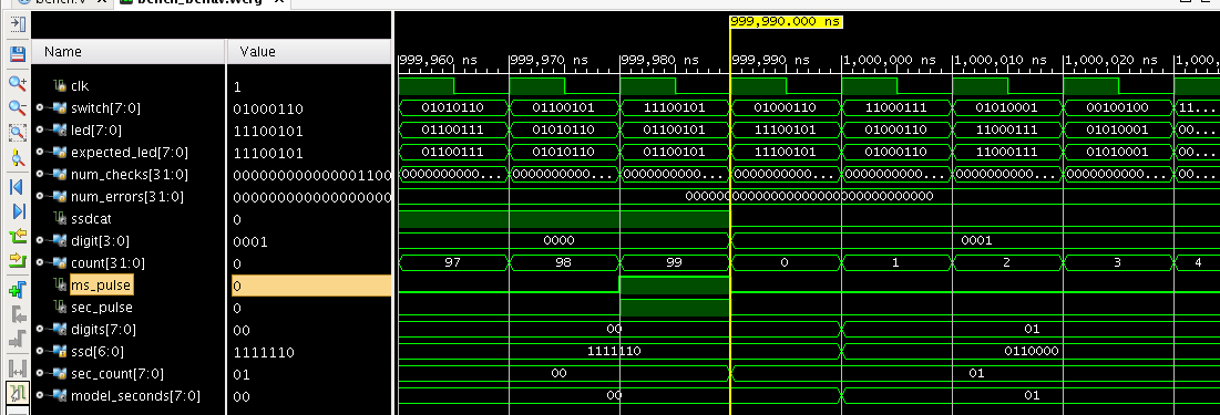
What has gone wrong? Obviously with 18136 failures out of 4000000 comparisons things are mostly correct. Let’s look at the waveform from the simulation at time 1,000,000ns. Really zoom in to that time so you only see 10 or so clock cycles. Here is what my simulation is showing me.
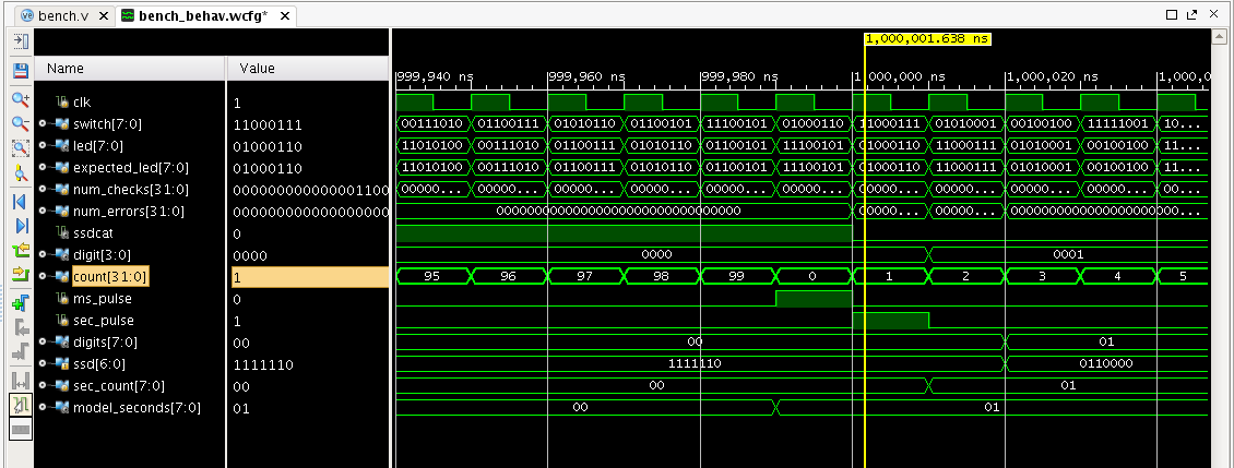
Well, I can see why sec_count does not match model_seconds. The timing is off by a few clock cycles. This is due to some latency in the design. We can correct for this in a number of ways. We can reduce the latency in the design, or we can add latency to the model. Or both. One thing I notice is that the ms_pulse and sec_pulse signals are not coincident. This may be OK, but we could reduce the latency some by bringing in sec_pulse by one clock cycle. This also makes the design a little bit cleaner and in a complex design might help keep things simple.
Let’s look again at the code which generates ms_pulse.
  integer     count = 0;
  reg 	      ms_pulse = 0;
  always @(posedge clk)
    begin
      ms_pulse <= 0;
      if (count == ms_limit-1)
	begin
	  count <= 0;
	  ms_pulse <= 1;
	end
      else
	count <= count+1;
    end
Notice how ms_pulse is placed in a flip-flop? Also, notice how it is high when the count value is zero. Let’s change the definition of ms_pulse to be combinational. This will eliminate the delay of one clock.
The result looks like this.
  integer count = 0;
  wire ms_pulse = count == ms_limit-1;
  always @(posedge clk)
    if (ms_pulse)
      count <= 0;
    else
      count <= count+1;
Hey, that is even simpler to code. Let’s run our simulation and see if we have changed things.
Yep, we pulled that ms_pulse signal in one cycle. And we got rid of one of the error messages. Still our output only updates after the sec_pulse signal. Can we pull that one in too? It looks like we can pull the same trick with that. Here is the modified code.
  integer ms_count = 0;
  wire sec_pulse = ms_count == 999;
  always @(posedge clk)
    if (ms_pulse)
      if (sec_pulse)
	ms_count <= 0;
      else
	ms_count <= ms_count+1;
Let’s run that. Here are the first error messages and the waveform. It looks like we have introduced a bug. Notice how sec_count increments every clock cycle before the ms_pulse signal triggers. You can see it in the waveform.
run 1 ms
ERROR: digits value 10 does not match expected value 0 at time 999170.000000ns
ERROR: digits value 10 does not match expected value 0 at time 999180.000000ns
ERROR: digits value 10 does not match expected value 0 at time 999190.000000ns
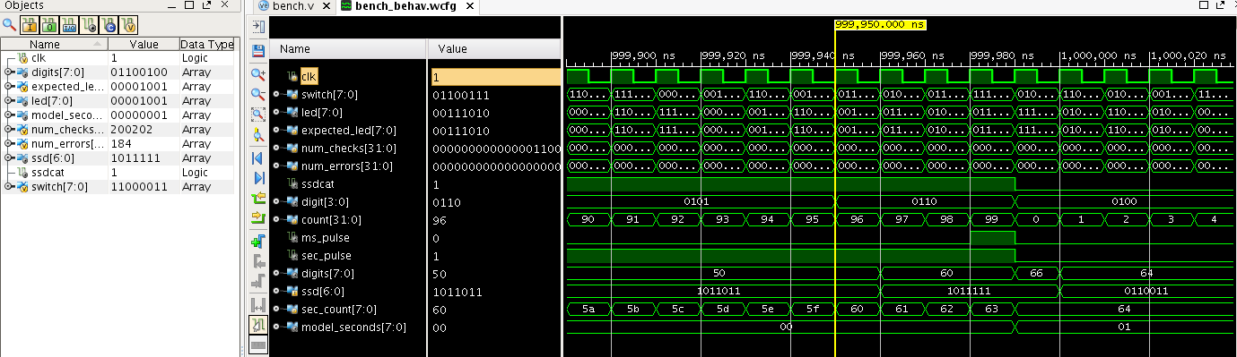
If you look at sec_pulse you see it is no longer a pulse. This causes sec_count to increment rapidly. We need to condition sec_pulse to now only happen when ms_pulse is also happening. Something like this.
wire sec_pulse = ms_count == 999 && ms_pulse;Let’s make the change and run again. Here is the waveform.
Notice that the pulses are each for a single clock and they all line up? We are still getting an error message since things still don’t quite line up. This is because there is still a delay of a clock when encoding the seven segment outputs. We should leave that clock in there if possible. It lets the outputs of the FPGA leave the chip on the rising edge of a clock. This will hide any internal delays and make interfacing to the outside world easier. It doesn’t much matter for an LED, but for faster devices it can really help.
So, we need to add a cycle of delay to the test bench. Let’s do that now. Just change the model to register the seconds output on the rising edge of clock. Like this.
  always @(posedge clk)
    seconds <= counter / (ms_limit * 1000);
Be sure to also change the output declaration for seconds to be a reg.
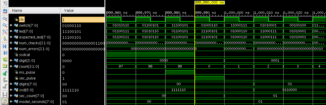
Rerunning the simulation causes the errors we were attacking to go away. Here is the waveform right at 1ms.
Tracking more bugs
It looks like we still have some errors though. Here is the next error message.
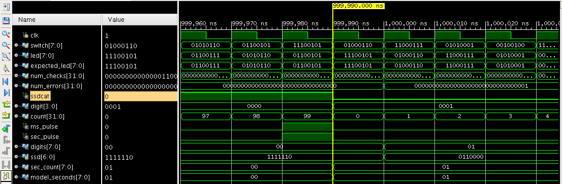
ERROR: digits value 11 does not match expected value 1 at time 1001000.000000nsLet’s zoom in on that time and see what’s going on.
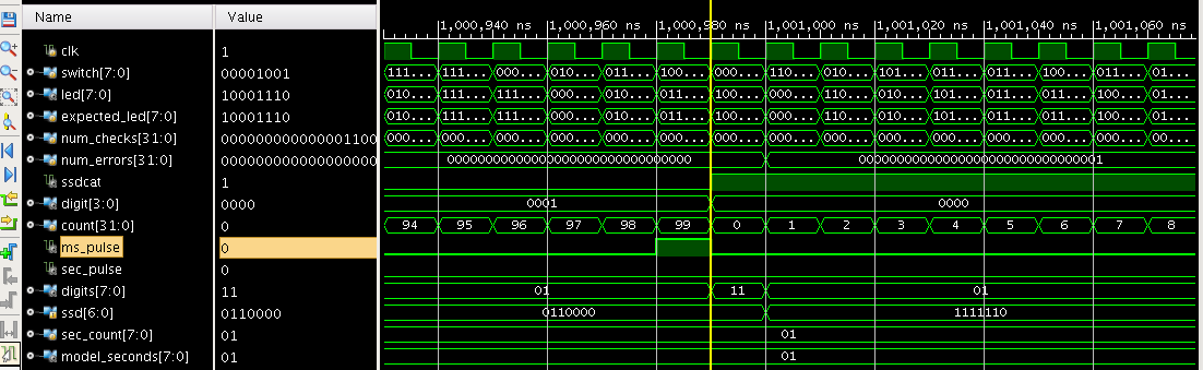
Look at what happens to the digits value. Right as ssdcat rises it has a value of ‘h11, when the correct value is ‘h01. It then goes back to ‘h01 the following clock cycle. It looks like the ssdcat signal is leading the ssd output by a clock cycle. This is causing the wrong data to go to the display for a clock cycle. You could never see this on the display and might not matter in this instance. But usually you are sending data to another chip and those can see what is happening on every cycle and every cycle needs to be correct.
The bug is caused by our ssdcat output not having the same pipeline delay as the ssd output. We can fix that by delaying it one clock. Here is how I chose to do it.
  reg  ms_pulse_delay = 0;
  always @(posedge clk)
    ms_pulse_delay <= ms_pulse;

  initial ssdcat = 0;
  always @(posedge clk)
    if (ms_pulse_delay) ssdcat <= ~ssdcat;
Delaying the ssdcat signal seems to do the trick. But if you simulate even further you will find another group of error messages. Here they are
ERROR: digits value 0 does not match expected value 10 at time 16000010.000000ns
ERROR: digits value 0 does not match expected value 10 at time 16000020.000000ns
ERROR: digits value 0 does not match expected value 10 at time 16000030.000000ns
You know the drill by now. Let’s look at the waveform around 16ms into the simulation. Here is what I have.
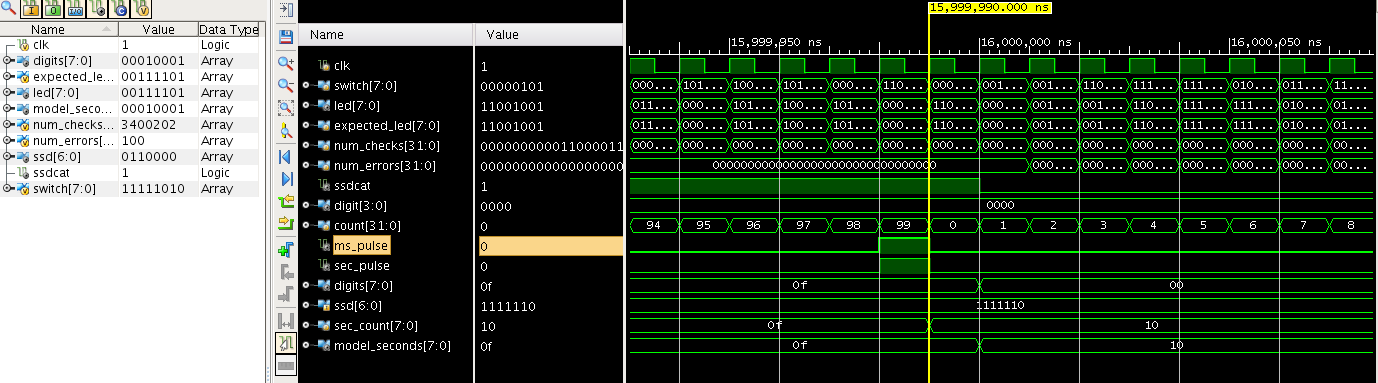
Sure enough the digits output goes back to ‘h00 rather than properly wrapping to ‘h10. Why does it do this? The error persists for a millisecond and then goes away. If you dig into it a little you will realize that only one of the hex digits in the digits signal can change at a time. The one that changes is indicated by ssdcat. Once ssdcat changes state again the digit then gets updated and the messages go away – until of course we go from ‘h1f to ‘h20. The fix for this is to be a little more selective on when we check the digits. We can update this in our test bench.
Here is the modified check that I have now. I use two four bit values to hold the digits I want to check, one from the model and one from the FPGA.
  reg [3:0] check_digits;
  reg [3:0] check_model_digits;
  always @(posedge clk)
    begin
      check_digits = ssdcat ? digits[7:4] : digits[3:0];
      check_model_digits = ssdcat ? model_seconds[7:4] : model_seconds[3:0];
      num_checks = num_checks+1;
      if (check_digits != check_model_digits)
	begin
	  if (num_errors < 100)
	    $display("ERROR: check_digits value %0x does not match expected check_model_digits value %0x at time %0.0fns",
		     check_digits,check_model_digits,$realtime);
	  num_errors = num_errors+1;
	end
    end
I also took the liberty of limiting the number of errors that are printed out to keep from having tens of thousands of error lines in my log file. When I run the test with these changes I get the beautiful message below.
run all
Simulation complete at time 20000000.000000ns.
*** Simulation PASSED 0/4000002
$finish called at time : 20 ms : File "/home/pete/tutorial6/tutorial6.srcs/sim_1/new/bench.v" Line 89
run: Time (s): cpu = 00:00:15 ; elapsed = 00:00:14 . Memory (MB): peak = 6060.445 ; gain = 0.000 ; free physical = 1068 ; free virtual = 4552
Four million checks and every one passed. Here are my files for this tutorial.
Hi Pete,
Does the counter model run off the 100MHz clock that you created earlier in the testbench?
Thanks,
Tim
Yes, if you look in the test bench you will see it instantiate the model and pass the same clock in. The model uses the same parameter to control the time speedup as the FPGA. This keeps them in sync.
Dear sir. Pete Johnson,
This Lab is challenged but very interesting.
Thank you!!
Dear sir. Pete Johnson,
Why don’t we use the simple “Second Counter Model” instead of the complicated “top” for counting second?
Pingback: Lab 5 and 6: Counting Second – tranminhhai
I don’t quite follow what you are asking? Can you rephrase the question and maybe make it a little longer? That way I would have a better chance understanding what you are asking. Also, should I address you as Minhhai or Tran? It is not always easy to tell.
Thanks,
-Pete
Hi Pete,
I tried your design and set the following constraints:
create_clock -period 10 [get_ports clk]
create_clock -period 10 -name virtual_clk
set_input_delay -clock virtual_clk 0 [get_ports switch]
set_output_delay -clock virtual_clk 0 [get_ports led]
set_output_delay -clock virtual_clk 0 [get_ports ssdcat]
set_output_delay -clock virtual_clk 0 [get_ports ssd]
There is some setup violation (max slack -1.333ns on my Zedboard). I know (or at least, I assume) that the PmodSSD is combinatoric so there is no clock there, but why didn’t you put the above constraints in your file? Vivado gives a warning saying that the output should always be constrained. Thanks.
The switches are asynchronous. They don’t have any defined timing with respect to the clock. You could set a constraint on those inputs but it wouldn’t really accomplish anything. And they would be incorrect anyway.
As for the others, they are outputs which will be viewed by humans. Again, pretty asynchronous to the internal clock. But also working on timescales which are many orders of magnitude larger than what the FPGA can accomplish. The human visual system is going to have a difficult time measuring anything less than about 50ms. That’s at lease 10,000 times slower than any result the FPGA will produce.
In general though, you should have constraints for all your inputs and outputs. I think Vivado is erring on the side of caution with this. I have seen FPGA designs with no constraints and designers who thought that was not an issue. Clearly in the vast majority of real design cases that is incorrect.
Thank you for your opinion, Pete.
Thank’s for the great tutorial! I am making my way through it.
I am using the the open source tool chain icestorm to getting a little bit into the FPGA topic 🙂
I have used icestorm with the Lattice ICE40 board and I like it a lot. I think a command line environment is actually simpler than the Vivado GUI for beginning users. Fewer distractions.
Hi Pete,
this tutorial is very great. I mistook the code:
wire ms_pulse = count == ms_limit-1;
against
wire ms_pulse = count = ms_limit-1;
And wondered, how could it work at all.
After second time of reading, I noticed my failure.
So in my code, for more clearance to myself, I wrote:
wire ms_pulse = (count == ms_limit-1);
and the same for second pulse
wire sec_pulse = (ms_count == 999 && ms_pulse);
That’s fine to do. In many languages and assignment is also an expression. This is true in C and C++. But in Verilog an assignment is only a statement and not an expression. Think about this code
It is similar to the assign but it is a little more confusing because the same symbol is the assignment operator and the less than operator. If you code in Verilog for a while you get used to this and it doesn’t seem as confusing.
I’m glad you’re enjoying the tutorials.
-Pete