
Now that we have our top watch working, we’re all done, right?
Not quite. Mechanical switches and buttons have a property called bounce. Bounce means the switch won’t go cleanly from open to closed or vice versa. Instead, it bounces between the two states for a little while. We just want to see a single rise or fall when the switch closes or opens.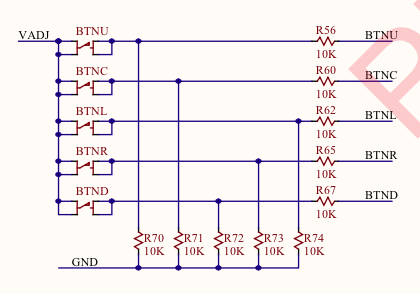
There are a number of ways to address the issue of switch bounce. These methods are referred to as debouncing the switch. In ZedBoard, the designers placed 10KΩ series resistors between the buttons and the FPGA. This helps filter out some of the noise. However, is it enough?
Let’s construct a circuit which looks for pushbutton bouncing on the ZedBoard.
Measuring Bounce
Here, we’re going to use the same module declaration and constraints as our previous tutorial. We’ll also use the logic to look for a rising edge on the pushbutton inputs, as well as adding signals to detect the falling edge as well. Then we’ll use the logic to drive the SSD output ssd and ssdcat. Here’s what I have for those parts of the design:
`timescale 1ns / 1ns
module top
  (
   input clk,
   input [7:0] switch,
   input [4:0] btn,
   output reg [7:0] led,
   output reg [6:0] ssd,
   output reg ssdcat
   );

  wire btnl = btn[0];
  wire btnu = btn[1];
  wire btnr = btn[2];
  wire btnd = btn[3];
  wire btnc = btn[4];

  reg [1:0] btnl_shift;
  always @(posedge clk)
    btnl_shift <= {btnl_shift,btnl};
  wire btnl_rise = btnl_shift == 2'b01;
  wire btnl_fall = btnl_shift == 2'b10;

  reg [1:0] btnc_shift;
  always @(posedge clk)
    btnc_shift <= {btnc_shift,btnc};
  wire btnc_rise = btnc_shift == 2'b01;
  wire btnc_fall = btnc_shift == 2'b10;

  reg [1:0] btnr_shift;
  always @(posedge clk)
    btnr_shift <= {btnr_shift,btnr};
  wire btnr_rise = btnr_shift == 2'b01;
  wire btnr_fall = btnr_shift == 2'b10;

  wire [3:0]  digit;
  always @(posedge clk)
    case (digit)
      0: ssd <= 7'b1111110;
      1: ssd <= 7'b0110000;
      2: ssd <= 7'b1101101;
      3: ssd <= 7'b1111001;
      4: ssd <= 7'b0110011;
      5: ssd <= 7'b1011011;
      6: ssd <= 7'b1011111;
      7: ssd <= 7'b1110000;
      8: ssd <= 7'b1111111;
      9: ssd <= 7'b1110011;
      10: ssd <= 7'b1110111;
      11: ssd <= 7'b0011111;
      12: ssd <= 7'b1001110;
      13: ssd <= 7'b0111101;
      14: ssd <= 7'b1001111;
      15: ssd <= 7'b1000111;
    endcase

  reg [0:$clog2(ms_limit)-1] count = 0;
  always @(posedge clk) count <= count+1;
  always @(posedge clk) ssdcat <= count[0];
Concept
We want to implement a counter that counts for some period of time long enough for all the bouncing to finish. This timer will start whenever the button input rises or falls. It will stop if the button input bounces before the counter expires. The timer duration we’ll be using is 10ms– plenty of time for the switch to stop bouncing. Now, there are two timer values which we need to store. If the button input is rising and the button bounces, then we will see the input fall, then rise again. Conversely, if the input is falling, it will bounce high and then low again. This means we will also need to remember these two values. Here is the declaration of all this in Verilog:
  localparam bounce_limit = 10*ms_limit;
  reg [$clog2(bounce_limit)-1:0] bounce_count = 0;
  wire bounce_limit_reached = bounce_count == bounce_limit-1;
  reg [$clog2(bounce_limit)-1:0] period0 = 0;
  reg [$clog2(bounce_limit)-1:0] period1 = 0;
In addition, we need a flag to indicate that we have detected a bounce on either the rise or fall of the button input:
  reg triggered_rise = 0;
  reg triggered_fall = 0;
State Machine
To control the operation of the counters and the updating of the period registers, we’ll use a type of logic called a state machine. A state machine consists of a variable which holds a state value, a set of inputs, and a set of outputs or actions. The state machine may transition between states in response to different inputs. Usually, a state machine is represented in documentation by a state transition diagram. We need a state machine with four states. The state machine will use an idle state when looking for a button press. Once the button gets pressed, the state machines enters the wait_1st and waits for a bounce. If the timer expires, then the state machine returns to the idle state. Otherwise, if a transition is detected before the timer expires, the state machine stores the count value in period0 and enters the wait_2nd state. In the wait_2nd state, the state machine waits for another transition of the button input. This input will happen because a transition within 10 ms is always caused by a bounce, not the button being legitimately pressed and released. When the button transition takes place, the state machine updates period1 and enters the triggered state. The state machine lights an LED to indicate that a bounce was detected and then waits for a rising edge on the left button to reset the state machine and reenter the idle state. Here is the state transition diagram. 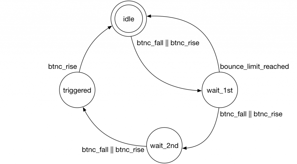
To code a state machine, we need to define the state variable first. I like to use an integer for FPGA coding, since it will always be large enough to hold all the states. The synthesis tool will re-encode the state values to be efficient for hardware, so it doesn’t really matter if you use an integer– you won’t be wasting any space in the FPGA. I also like to use localparam declarations of the states themselves. This lets me assign a symbolic value instead of a number, which will make the code more readable. Let’s go ahead and do that now.
  localparam idle_state = 0;
  localparam wait_1st_state = 1;
  localparam wait_2nd_state = 2;
  localparam triggered_state = 3;
  integer state = idle_state;
Next we code an always block which contains a case statement which selects actions based on the current state.
  always @(posedge clk)
    case(state)
We then have entries in the case statement for each state. This next part is pretty simple. Here is the entry for the idle state. When in the idle state we reset the bounce counter, the period counters and the triggered flags. If we detect an edge transition on the center button, we enter the wait_1st state. Here’s the code:
      idle_state:
	begin
	  bounce_count <= 0;
	  period0 <= 0;
	  period1 <= 0;
	  triggered_rise <= 0;
	  triggered_fall <= 0;
	  if (btnc_fall || btnc_rise)
	    begin
	      triggered_rise <= btnc_rise;
	      triggered_fall <= btnc_fall;
	      state <= wait_1st_state;
	    end
	end
Once we’re in the wait_1st state, we’re going to increment the bounce count every clock, then test to see if we either have reached the bounce limit (in which case we go back to the idle state), or we detect another edge on the center button (in which case we record the current bounce count value in the period0 register and enter the wait_2nd state).
      wait_1st_state:
	begin
	  bounce_count <= bounce_count+1;
	  if (bounce_limit_reached)
	    begin
	      state <= idle_state;
	    end
	  else if (btnc_rise || btnc_fall)
	    begin
	      period0 <= bounce_count;
              bounce_count <= 1;
	      state <= wait_2nd_state;
	    end
	end
The wait_2nd state is pretty similar. The exception is that we don’t go back to idle on a timeout. The only way to exit is to detect an edge on the center button and enter the triggered state. We also update the period1 register when this happens.
      wait_2nd_state:
	begin
	  bounce_count <= bounce_count+1;
	  if (btnc_rise || btnc_fall)
	    begin
	      period1 <= bounce_count;
	      state <= triggered_state;
	    end
	end
The final state is the triggered state. Here we just wait for the user to press the left button, whereupon we enter the idle state again.
      triggered_state:
	if (btnl_rise)
	  begin
	    state <= idle_state;
	  end
Don’t forget to end the case statement with the encase keyword.
Simulation
Does it work so far? In order to tell, we should do some simulation. Let’s start a new test bench similar to the one we used before. Declare the module and the clock, inputs, and outputs to the top module. Remember, the inputs to the module should be declared as reg type signals and the outputs from the module should be wire. This is because the test bench is driving the module inputs and the top module is driving its outputs.
Here is what I have for that:
`timescale 1ns / 1ns
module bench;
  reg clk = 1;
  always #5 clk = ~clk;

  reg [4:0] btn = 0;
  reg [7:0] switch = 0;
  wire [7:0] led;
  wire 	     ssdcat;
  wire [6:0] ssd;

  top #(.ms_limit(100)) top
    (
     .clk(clk),
     .btn(btn),
     .switch(switch),
     .led(led),
     .ssd(ssd),
     .ssdcat(ssdcat)
     );
Next, I’ll introduce you to the concept of a Verilog task. A task is just a procedural block with a name and a set of input and output values. You can only call a task in places where you can also put a begin end block. Tasks can be synthesizable, in which case all the RTL restrictions apply (like no # delays), or they can be used in test benches (in which case you can use all language features). Below is a task which presses a button with the possibility of bouncing. The task takes three input values: which button to press, how many clocks to wait before bouncing the button low, and how many clocks to wait before returning the button to the high position. Sometimes you don’t want the switch to bounce. In this case, you specify a zero for the bounce time. In all cases, the second bounce parameter specifies how long to wait to return the button to high after the bounce. If there is no bounce then this input is ignored. Here is the code:
  task press_button;
    input integer button;
    input integer bounce0;
    input integer bounce1;
    begin
      btn[button] <= 1;
      if (bounce0 > 0)
	begin
	  repeat(bounce0) @(posedge clk);
	  btn[button] <= 0;
	  repeat(bounce1) @(posedge clk);
	  btn[button] <= 1;
	end
    end
  endtask
Note that the inputs and outputs of the task are syntactically different from module input and output ports. Why? I have no idea. Anyway, we now have a task to press a button. We also need a task to release a button. Go ahead and code that now. Call the task release_button.
Now, the way I’ve coded things, the left button is btw[0], and the center button (which we are measuring for bouncing) is btw[4]. If our logic works correctly, we’ll need to use the left button to clear the state machine back to its initial state. So, I have a task that will press the left button. Since this button does not have the debounce state machine hooked to it, we can press it as fast as we want in simulation and not have the design think it is a button bounce. I’ll create a task called clear_trigger which will press and release the left button. Now, I can use the press_button and release_button tasks we defined earlier.
  task clear_trigger;
    begin
      press_button(0,0,0);
      repeat (10) @(posedge clk);
      release_button(0,0,0);
      repeat (10) @(posedge clk);
    end
  endtask
Now we need to press the center button with some bounce, clear the trigger condition, release the button with some bounce, and clear that trigger condition. This will form the beginnings of a test. Here is what I have for that:
  initial
    begin
      repeat (10) @(posedge clk);

      press_button(4,100,100);
      repeat (10) @(posedge clk);
      clear_trigger;

      release_button(4,100,100);
      repeat (10) @(posedge clk);
      clear_trigger;

      repeat (10) @(posedge clk);
      $finish;
    end
The repeat statements just give the simulation enough time to let all the signals propagate through the design. Remember, it takes a few clocks for the logic to even see that the button was pressed, and then another clock or two to get the state machine to transition. In fact, the repeat clock cycle idiom is so common, I often define a task in my test bench called spin which simply takes the number of clocks as input and has a simple repeat statement that repeatedly waits the requested number of clock cycles. That way, rather than writing repeat (10) @(posedge clk);, I can just write spin(10);.
Don’t forget to add the endmodule keyword at the end of the test bench.
Go ahead and run your simulation. I added the signals period0, period1, state, and bounce_count from the top module with the radix set to unsigned decimal. Here is what my waveform looks like:
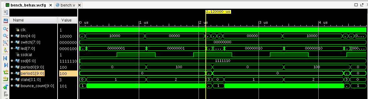
I can see the correct period values in the waveform so everything looks good. Still, we’re not quite there yet. We don’t have any way to see the period registers in the real design. And we don’t have any way for the test to tell if it worked without looking into the top module. We will fix that in the next tutorial.
Here are my files that I have for this tutorial.
Thanks for your lessons! Is in the transition diagram in state “triggered” we need to write btnl_rise (now btnc_rise)?