
In this tutorial, we will build on our counter from the last tutorial to add the ability to start, stop, and reset the time counter. Essentially, we’re going to make a stopwatch.
Adding the Buttons
The ZedBoard has five pushbutton inputs that go to the FPGA. There are two additional pushbuttons, which are for use by the ARM processor that cannot be used by the FPGA fabric. We need to declare the button inputs to the module. We can do this either as five separate inputs or a 5-bit bus. I prefer the bus method.
Just add the following to the port list:
input [4:0] btn,Also, it can be nice to refer to the buttons symbolically as well, so I added the following wire definitions too.
  wire btnl = btn[0];
  wire btnu = btn[1];
  wire btnr = btn[2];
  wire btnd = btn[3];
  wire btnc = btn[4];
Of course, we need to add the design constraints to declare the IO type and which pin the inputs are connected to. Modify the top.xdc file to add the following lines:
set_property IOSTANDARD LVCMOS25 [get_ports btn]
set_property PACKAGE_PIN P16 [get_ports {btn[4]}]
set_property PACKAGE_PIN R16 [get_ports {btn[3]}]
set_property PACKAGE_PIN R18 [get_ports {btn[2]}]
set_property PACKAGE_PIN T18 [get_ports {btn[1]}]
set_property PACKAGE_PIN N15 [get_ports {btn[0]}]
Next, we’ll need to look at the buttons. I am going to choose the left button to reset the counter, the center button to stop the counter, and the right button to start the counter. When the button is pressed, the corresponding input value goes high. When the button is released, the button goes low again.
First, we’ll need some logic to detect the rising edge of a button.
Detecting the Rising Edge
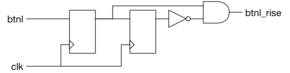 An important thing to note is that the button can be pressed at any time, so it’s impossible to say when the signal will arrive with respect to the clock. This type of signal is referred to as asynchronous. It is critically important for your design reliability that you deal with any asynchronous signals by bringing them on chip, then immediately sampling them in a single flip-flop. This way, you’ll synchronize the signal to your clock domain. Once we’ve synchronized the button input, we can start looking to see if the button has risen. The schematic will help to illustrate what we are looking for.
Here is the Verilog code that implements the schematic:
  reg [1:0] btnl_shift;
  always @(posedge clk)
    btnl_shift <= {btnl_shift,btnl};
  wire btnl_rise = btnl_shift == 2'b01;
The first line declares a 2-bit register. We then define the register to be set top its value shifted left by one and the button input shifted in. The curly-braces indicate that the values within are to be concatenated together to form a wider bus. So the expression on the right has a width of three bits. This is then assigned back into the 2-bit shift register. This has the effect of setting bit zero of the shift register to the button input and bit one of the shift register to the previous value for bit zero.
We could code the assignment to btnl_rise like this:
wire btnl_rise = btnl_shift[0] & ~btnl_shift[1];However, I think the comparison to 2’b01 is much cleaner and better indicates to the reader what you’re really looking for.
Go ahead and add code for the center and right buttons.
Starting and Stopping the Count
To start and stop the counter we just need to start and stop time. The thing that really does that in our design is the counter count. It just counts up to ms_limit-1, then wraps back to zero. It also generates the millisecond pulse signal ms_pulse. To get the counter to stop and start, we create a count_enable signal. This will initially be set to zero, and will then go high when btnr_rise occurs, and low when btnc_rise occurs.
  reg count_enable = 0;
  always @(posedge clk)
    if (btnr_rise)
      count_enable <= 1;
    else if (btnc_rise)
      count_enable <= 0;
Now, we modify the counter to hold whenever the enable signal is not active. Like this:
  integer count = 0;
  wire ms_pulse = count == ms_limit-1;
  always @(posedge clk)
    if (count_enable)
      if (ms_pulse)
	count <= 0;
      else
	count <= count+1;
Go ahead and build the design and try it out. Can you start and stop the counter? There seems to be a bug. Can you figure out what it is? In case you didn’t actually try the design, the symptom is that you only see one digit displayed when the counter is stopped. Why is that?
Seeing Both Digits Again
If we stop the counter then we also stop the ssdcat output which lets us control both digits, causing our bug. What should we do? Simple: use another counter for that function. We could just duplicate the millisecond counter we had before and use that, but I want to try something a little more efficient. The exact frequency for the ssdcat signal isn’t all that important: it only needs to be above about 60Hz and below 1kHz. Let’s use a counter which naturally wraps, and then not explicitly do a comparison to ms_limit to make it wrap early. Then, we’ll just use the most significant bit of the counter for the ssdcat output. How many bits should we use? Well, since ms_limit is 100,000 in the FPGA and we can represent that in 17 bits, a 17-bit counter should work.
Not so fast there. Remember, ms_limit is a parameter. In our test bench we set it at a much smaller number (100). If we use the real milliseconds in our simulation, which runs at a 1000x faster rate, then our ssdcat signal will hardly change at all in the simulation. So we should use our parameter for ms_limit in some way for this counter as well. The solution is to just make the counter big enough to count to the next higher power of two after ms_limit. Or, in other words, the number of bits for our counter should be the log of ms_limit. Here’s the code.
  reg [0:$clog2(ms_limit)-1] ssdcat_count = 0;
  always @(posedge clk)
    ssdcat_count <= ssdcat_count+1;

  initial ssdcat = 0;
  always @(posedge clk)
    ssdcat <= ssdcat_count[0];
Notice how, in the declaration for ssdcat_count, the bit width specification is the reverse of what we normally do. A lot of people are confused as to what it means when you do this, but it is actually quite simple. When you specify a width for a bus in Verilog, the number before the colon is the number you are giving to the most significant bit, and the number after the colon is the number you are giving to the least significant bit. In this case, I am specifying that the most significant bit of the counter ssdcat_count is zero. This is convenient because later on, I want to assign the most significant bit to ssdcat. If I do it this way, I can change the size of ssdcat_count later, and I won’t have to change the reference to the most significant bit– it will always be zero, no matter what the width is. Actually, we’re going to need to change the references in the switch statement that generates digit to use ssdcat_count[0] now, instead of ssdcat_pre which we have replaced.
Let’s try the design out again.
Adding the Clear Button
To add the “clear” button, we obviously need to clear our counter. That’s pretty easy:
  integer count = 0;
  wire ms_pulse = count == ms_limit-1;
  always @(posedge clk)
    if (btnl_rise)
      count <= 0;
    else if (count_enable)
      if (ms_pulse)
	count <= 0;
      else
	count <= count+1;
However, that doesn’t really do what we want. We’ll also need to clear the BCD digits. Let’s modify our bcd_digit module to add a reset signal. Add an input port called reset, then add the test for reset and clear the digit value when the reset input is high. Here is what I have:
  always @(posedge clk)
    if (reset)
      digit <= 0;
    else if (carry_in)
      if (carry_out)
	digit <= 0;
      else
	digit <= digit+1;
Now, we just need to pass the btnl_rise signal into the bcd_digit module. Let’s do that now. However, did you notice how the nine instances of bcd_digit are almost all the same? We can use a Verilog generate construct to simplify these instantiations. The generate construct allows you to instantiate the bcd_digit modules inside a for loop. Here’s what it looks like:
  genvar i;
  generate
    for (i=0; i<num_digits; i=i+1)
      bcd_digit #(10) bcd_digit
	(
	 .clk(clk),
	 .carry_in(carry[i]),
	 .reset(btnl_rise),
	 .digit(time_digits[i*4+:4]),
	 .carry_out(carry[i+1])
	 );
  endgenerate
The genvar statement declares a variable i that we will use in the generate for loop. The generate block is started with the keyword generate, and concluded with the keyword endgenerate. We’ll use a for loop to iterate num_digits times, and inside the loop, we instantiate the bcd_digit module. Also, note the new syntax for selecting the part of time_digits we want the instance to drive. The syntax is vector[bit+:width]. This syntax allows you to dynamically get to a part of a bus. In our case, the bit is given by the expression i*4, and the width is 4. Why not just use the expression time_digits[i*4+3:i*4], you might ask? The answer is a little esoteric. Still, it’s worth explaining. Doing this type of selection only really makes sense when the width of the selection is constant. That is, it can’t change for a given set of parameters or local parameters. The simulator and synthesis tool must be able to figure out what the number is when the design is compiled, and it can’t change after that. The bit selection can be dynamic. By specifying a bit and a width, you allow the compiler to understand whether the width is actually static. If you tell it i*4+3 and i*4, then the compiler would have to somehow figure out that (i*4+3)-(i*4) is equal to 3 for all possible values of i, so therefore the width must always be 4. It is just too difficult to write a compiler that can figure this out in all possible cases. So, because of this, we have the alternative syntax.
There are, however, two issues with this code. The first is that we exceed the bounds of the carry signal when i has the value 8. We’ll try to drive the carry out, which is unused, into carry[9], which doesn’t exist. Before, we had simply left this unconnected. The simplest solution is to just declare carry to be one bit wider. So its declaration changes to this:
wire [num_digits:0] carry;That was easy. Here’s our next issue: two of our digits need a parameter value of six, not 10. How do we do that? My solution is to declare a localparam value, which indicates which digits should wrap at 10 and which should wrap at six. Now, we can use this parameter inside the for loop. Then we change the instantiation of bcd_digit to be a little smarter.
  localparam wrap_at_six = 9'b001010000;

  genvar i;
  generate
    for (i=0; i<num_digits; i=i+1)
      bcd_digit #(wrap_at_six[i] ? 6 : 10) bcd_digit
	(
	 .clk(clk),
	 .carry_in(carry[i]),
	 .reset(btnl_rise),
	 .digit(time_digits[i*4+:4]),
	 .carry_out(carry[i+1])
	 );
  endgenerate
Files
Here are the files that I have for this tutorial:
Thank you for this tutorial!
This tutorial is not easy to digest (for me) because the code is so smart.
Hello Pete,
Does the “rising edge detector” still work reliably if I remove the left flip-flop (only use a flip-flop) ?
No, you need the first flip-flop for the design to work. Imagine the button input arriving just before the rising edge of clock. The pulse will go high, but only for a very short time and then it will go low again after the flip-flop changes to a 1. This pulse will not be detected by other logic being clocked off the clock.
Pingback: Rising Edge Detector – tranminhhai
Pingback: Detecting the rising edge of a short pulse | Beyond Circuits