
Clocking
Until now, we have just been using the sck signal, which is sent by the I2S master. This has kept things simple, but is probably not what we want to do in real life.
Inside an FPGA, there may be tens of thousands (or even hundreds of thousands) of flip-flops all running off a single clock. The clock has to arrive at each of those flip-flops at pretty much exactly the same time. By “pretty much exactly”, I mean down-to-the-nanosecond exactly. The FPGA achieves this by using special clock distribution networks within the FPGA. There’s a finite number of these networks– really, only a handful. So, it’s kind of a big deal to make a signal a clock. In addition, multiple clocks increase the complexity of the static timing analysis which needs to occur when synthesizing the device. This can lead to subtle bugs in the design. In short, you really want to minimize the number of clocks in a design.
But what can we do? The I2S interface uses a clock. Doesn’t that mean we need to use that clock signal? Not really. The sck signal is really pretty slow in reality. Normally it is 48 times the audio sample rate, which is, at most, 48KHz. That is 2.3MHz. Maybe in a crazy world where you have 32 bit samples and a 96KHz sample rate you might get it up to the blazing speed of 6.144MHz. Not really all that fast, by FPGA standards.
SCK edge detect circuit
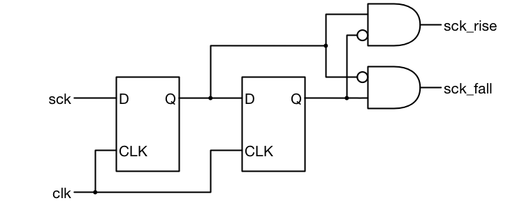
We can fix this by sampling the sck signal with a much faster FPGA clock. This will be more convenient for us to use. Since sck is an asynchronous signal, it is critical that it only go to one flip-flop in our design. If sck went to two flip-flops, if it rose at the same time as clk, it might get clocked in to one flip-flop but not the other. The circuit shown to the right safely samples the sck signal and produces two signals in the clk clock domain which pulse whenever sck rises or falls.
We can now use those signals as enables to condition the always blocks we had before. In other words, we used to have this always block:
always @(posedge sck)
  wsd <= ws;
We could now use this one:
always @(posedge clk)
  if (sck_rise) wsd <= ws;
As long as our new clock clk is more than twice as fast as sck, the logic will still work.
Files
Here is the test for this version of the receiver.
In our next tutorial, we will add an AXI4 Streaming interface, so we can use our block in the Vivado IP Integrator tool.
Hi Pete,
Implemented the clock sync change without incident. While the data rate is slow, if pushed faster, one could de-skew the data from the clock by adding.
reg sdd;
always @(posedge clk)
sdd<=sd; // delay sd by one clk to remove 10ns skew
…
data_word[i] <= sdd; // where appropriate in code
The word select is (data word length)x slower so deskew could never make sense here.
Agree?
Eric
Yes, if you know that the data is stable when clock is changing you could do this. You would also need to do the same with the strobe signal.
Hi Pete,
Are there any relationships between the clk and sck? How many clocks in the system? Is the clk/sck rate fixed? You calculated sck speed based on the sample rate. So it seems it varies. How to determine which clock to use and what rate it should be? You did mention that sck is slower than clk.
Thanks,
Susan
The assumption is that clk is enough faster than sck to make the system work. There is no phase relationship between the two clocks. With the intended design the sck signal is really no longer a clock. It is a data input that is sampled on the rising edge of clk. Your new circuit should look for a rising edge on sck with the circuit shown in the figure and then use the resulting sck_rise and sck_fall signals as enables for the flip-flops that used to be clocked on sck.
Wrong solution. I realize that this is just a tutorial and is not designated for real audio use, but nevertheless, you insert an uncontrolled amount of jitter using asynchronous clocks – you may miss an edge, and the signal skews in time or even a sample is lost.
Good boys use MCLK. 🙂
I’m no audio expert so you shouldn’t rely too much on my design. But I don’t understand why the jitter on the data would matter. As long as you maintain proper setup and hold times on the data with respect to clock why does jitter on the data matter?
Look at my post above. You may miss or misplace an edge, moving the data in time. This is what audiophiles call The Horrible And Monstrous Jitter.
It’s audible, seriously.
And mclk nowadays is 22.579/24.576Mhz (tending to double), so it’s really better to establish one more clock domain.
If the FPGA is the I2S Master, we do not need to have this design right?
Yes, this block is for receiving I2S data.