
Installing PetaLinux
In this tutorial, we cover installing PetaLinux on your build machine and making a Linux build for your ZedBoard. We will then write some code to control the FPGA we built in the previous tutorial.
You can find the 2015.4 release of the PetaLinux tools here. You will need to download the PetaLinux Installed and the ZedBoard Board Support Package (BSP).
My Xilinx tools are installed in /tools/xilinx, so I’m going to install the PetaLinux tools in the same location. You should modify the commands below for your particular installation directory. After downloading the PetaLinux tools, run the following command to install them.
sudo ./petalinux-v2015.4-final-installer-dec.run /tools/xilinx
This will take quite a while to verify the package contents and then ask you to accept some license terms.
Once the PetaLinux tools are installed, you also need to install the board support package. That is just a single file which I copied into the install area like this:
sudo cp Avnet-Digilent-ZedBoard-v2015-4-final.bsp /tools/xilinx
That should complete your PetaLinux installation.
The PetaLinux tools have a shell script which you can use to set your shell path and environment variables. To do that, run the following in your shell:
. /tools/xilinx/petalinux-v2015.4-final/settings.sh
You should ignore any warnings about no tftp server.
Creating a PetaLinux project
You use the petalinux-create command to create a project. Here is the command to build a project named zedboard_linux using the ZedBoard BSP:
petalinux-create --type project --name zedboard_linux --source \
/tools/xilinx/Avnet-Digilent-ZedBoard-v2015.4-final.bsp
This will create a new project directory called zedboard_linux.
Configuring your project
Once you have created your PetaLinux project, you need to configure the Linux build. To do that, you run the petalinux-config command like this. Remember that, in the previous tutorial, we exported our Vivado FPGA to SDK. We need to point the PetaLinux configuration process to that exported design. In the following, I have created the zedboard_linux project in the same directory where my Vivado project directory resides. So I used the following command:
petalinux-config --get-hw-description zedboard_spi/zedboard_spi.sdk \
--project zedboard_linux
This will bring up a Linux menuconfig utility. You can use this to configure options for your Linux build. For now, just use your arrow keys to select Exit and then press return.
We want to enable SSH, so we need to run petalinux-config again to configure the root filesystem to include the DropBear SSH server. Run the following command:
petalinux-config -c rootfs --project zedboard_linux
This will bring up a menuconfig screen that looks like this:
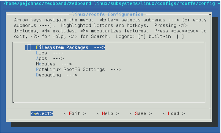
Press return to select Filesystem Packages, then select console/network, and then select dropbear. Use the arrow keys and spacebar to select both dropbear and the bropbear-openssh-sftp-server. Then select Exit. Continue to exit pages until you exit out of the menuconfig process. Select Yes to save.
This will configure the build to enable the ssh server and the ability to ssh out of the ZedBoard.
Building the Linux image
Now build the image with the following command:
petalinux-build --project zedboard_linux/
This will place the build products in the zedboard_linux/images/linux directory.
Booting in QEMU
PetaLinux can use an open source emulator called QEMU to boot your Linux build, which can be useful at this point to verify that the build was successful. To boot your newly built image, run the following command:
petalinux-boot --project zedboard_linux --qemu \
--image zedboard_linux/images/linux/zImage
This will show a bunch of boot information and eventually give you a login prompt. Late in the boot process, you should have seen a message about starting the Dropbear SSH server. Login as root with the password root. After logging in, you can browse around and run Linux commands. You can run ifconfig and netstat to see network settings. To exit QEMU, type control-A x.
Building the First Stage Boot Loader
In this step we use the Xilinx Software Development Kit (SDK) to build a First Stage Boot Loader (FSBL). The FSBL is the code that does the very first configuration of the ARM at boot and loads the Linux boot loader u-boot.
In the previous tutorial we exported our design to SDK. Now, from Vivado, go to the File menu and select Launch SDK. A dialog will pop up asking for the workspace and the exported location. Just use the defaults and click OK.
Notice that there is a system.hdf window which shows the address map of the FPGA that we built. Note that the addresses of the GPIO block which we instantiated show up in this list along with many other devices which are standard in the processor system.
Click File->New->Application Project. Name the project Zynq_FSBL and then click Next. Then select the template Zynq FSBL and click Finish. This will build the FSBL.
Packaging the Linux build and FPGA
In order to make a bootable image for our ZedBoard, we need to package the Linux image, the boot loader, and the FPGA image into a single file. We do that using the petalinux-package command.
petalinux-package --boot --format BIN --project zedboard_linux \
--fsbl zedboard_spi/zedboard_spi.sdk/Zynq_FSBL/Debug/Zynq_FSBL.elf \
--fpga zedboard_spi/zedboard_spi.runs/impl_1/system_wrapper.bit \
--u-boot
This command will build the BOOT.BIN file, which you need to copy to the SD card that you use with the ZedBoard. The command is a little odd in that it puts the file in your current directory and also puts a copy in the project images/linux directory. Also, if the BOOT.BIN file already exists, it will refuse to run unless you give it the –force option.
Copy the BOOT.BIN file containing the FSBL, FPGA image, and u-boot to the SD card you will be using on your ZedBoard. Also, copy the file zedboard_linux/images/linux/image.ub, which contains the Linux kernel and filesystem.
Booting the ZedBoard
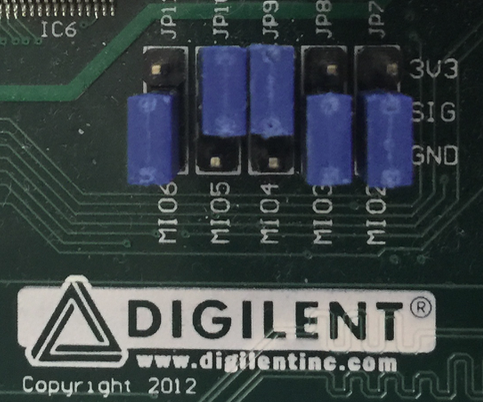 Be sure that your ZedBoard is configured for booting from the SD Card. The jumper settings should look like the figure to the right.
You also need to be sure that you have connected the micro USB cable from the UART USB connector located near the power switch to your computer. You need to configure a terminal emulator program to connect to the USB serial port at 115,200 baud. I usually use the Linux program screen to connect to the serial port. Move the SD card to the ZedBoard and power the board up. Unfortunately, the UART chip is powered off the main board power supply, rather than the USB interface. That means that, every time you power cycle the ZedBoard, you are disconnecting the USB UART from your computer. Also, you won’t be able to see the UART until you have powered on the ZedBoard.
I use the following command on my Mac to connect to the UART:
screen /dev/tty.usbmodem131 115200
The command is the same on Linux but the device file might be different. I’m not sure what the current terminal emulator of choice is on Windows. However, I can guarantee it will be more complicated to set up. For details on all of this, you can refer to the ZedBoard Cypress CY7C64225 USB-to-UART Setup Guide.
Conclusion
I hope that you were successful in booting your Linux build on your ZedBoard. In the next tutorial, we will be using SSH to log in to the ZedBoard and copy files over as well as connecting with a debugger.
Hi, I want to ask you about my project, to encoding my video file. I want do encoding its with Kvazaar (in C program) on my zynq zc702, but when I build with $petalinux-build, it’s still error (circullar, dependency drop). Thank you for your attention. Alex
Great tutorial. One thing that did not work for me as described is QEMU. I used “$ petalinux-boot –qemu –kernel” instead
Are you sure that your petalinux-build actually built the file zedboard_linux/images/linux/zImage? The –kernel option tells it to boot with the latest built image. But if you haven’t had a successful build I think it will boot with a prebuilt image.
I’m glad the tutorial was helpful.
Hello, Due to lockdown I don’t have access to actual ZedBoard. Can be perform a co-simulation with qumu emulating PS and vivado simulating the PL of zed board ?
Hi Pete, Can u please guide me how to build petalinux project for SD card. I am stuck with an error during petalinux build command. I am currently using 2020.2
It is probably possible to set something like that up. But it could be quite involved. You might want to look into Simics (https://www.windriver.com/products/simics/). Their tool does that type of thing. But it’s not cheap.
You need to make sure that the PS implements an SD device. And you need to make sure in petalinux-config that you specify the right device. Can you post the error message you are seeing? I have never seen an error related to this. Just a failure to boot from SD if you did it wrong. Also, what board are you targeting?
Your tutorials are the best. Super new to all of this. How do you find your device file of your connected board? Running Ubuntu 20.04
You should be able to see the Linux SPI device in /dev/spidev*. If it shows up there then Linux found the device and connected the user mode SPI driver to it.
Hi Pete, Thanks for your great tutorial. I have a question, so I’m trying to implement the example application (peekpoke) on Zynq ZCU104 board. I already succeed until petalinux-package part to make BOOT.BIN and before boot into the FPGA board, I want to check whether the peekpoke can be accessed using Qemu. Is it possible ? If yes, how to do it ?
(*Ps. I already make sure that peekpoke on petalinux-config -c rootfs was enabled)
Thank you for the tutorial. I follow the steps until the build step. When I try to build the project it fails and gives me the error messages bellow. Do you have any idea on what it means.
[ERROR] make[5]: *** [scripts/Makefile.host:100: scripts/dtc/dtc] Error 1
[ERROR] make[4]: *** [/opt/Xilinx/petalinux-v2015.4-final/components/linux-kernel/xlnx-4.0/scripts/Makefile.build:403: scripts/dtc] Error 2
[ERROR] make[3]: *** [/opt/Xilinx/petalinux-v2015.4-final/components/linux-kernel/xlnx-4.0/Makefile:557: scripts] Error 2
[ERROR] make[2]: *** [Makefile:145: sub-make] Error 2
[ERROR] make[1]: *** [Makefile:138: /home/ashura/Documents/Vivado_Projects/zedboard_linux/build/linux/kernel/xlnx-4.0/vmlinux] Error 2
ERROR: Failed to build linux
I am following everything as descried except for Linux OS I am using Ubuntu 22.04 LTS.
Hi, how do you if the board is running Linux correctly ?
version gives me this :
U-Boot 2021.01 (Jun 01 2021 – 11:54:06 +0000)
arm-xilinx-linux-gnueabi-gcc (GCC) 10.2.0
GNU ld (GNU Binutils) 2.35.1
Does it means that the board is currently running Linux ?
Thanks a lot for the help
Hi! I’m trying to understand what’s described in the “.bsp”. Petalinux must get info on what’s in the PL through “get-hw-description”, right? Is there something in the bsp that’s needed for petalinux to be able to build a working linux for the design?
Xilinx does a really bad job at describing this. I thought for a while “what must this magic be in a BSP file?”. Turns out it is just a tar file that is extracted after create-petalinux runs. You can put whatever you want in there and it will add to or replace everything that petalinux-create creates in the project directory. I think it’s actually better to not use a BSP file and instead use git or some other tool to track your changes when you edit a reference project directory. Then you can use git patch to patch the directory that petalinux-create makes. This way you have a better chance to merge your changes in with whatever petalinux-create produces rather than simply overwriting what it makes. This can help if you switch to a newer version of Petalinux.
If Linux is running you should see a login prompt or if you have auto login set you should see a bash prompt.
Sorry, it’s been a while since I have tested the tutorials so maybe there is an incompatibility with the newer tools. The problem here is that it can’t compile the device tree. That could possibly be caused by an error on the FPGA. It’s hard to say without digging in further. It’s on my todo list to update the tutorials when I get a chance. But I have been extremely busy.
It can be accessed. But keep in mind that when using QEMU you don’t have any FPGA hardware. So it would not be able to access devices on the FPGA.