
In Tutorial 24, I covered controlling a SPI device by just taking control of the memory mapped GPIO and bit-banging the SPI without a driver. In this tutorial, we’ll do things the “official” way, and use the one of the hard IP SPI controllers present on the ZYNQ chip. For this tutorial I am using Vivado 2016.2 and PetaLinux 2016.2.
Enabling the SPI controller
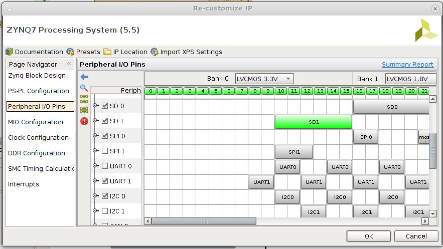
First you need to enable the SPI controller on the ZYNQ subsystem. Double-click on the ZYNQ processing subsystem in your Block Design in the IP Integrator window. This will bring up the IP configuration window. Click on the Peripheral I/O Pins section of the Page Navigator and check the box next to SPI 0. Note that Quad SPI or QSPI is unrelated to this discussion.
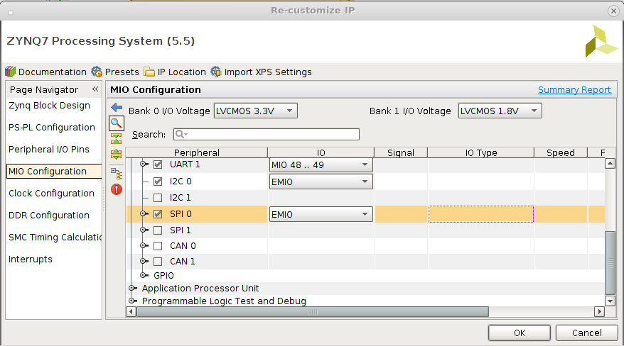
Next, go to the MIO Configuration section of the Page Navigator. Expand the I/O Peripherals section and scroll down to SPI 0. In the IO column make sure that EMIO is selected. This programs the SPI control signals to use the Programmable Logic rather than pins dedicated to the Processor Subsystem.
Making the connections
Next, you’re going to need to make ports on the FPGA which will connect to the SPI controller. For a SPI master, you’ll need at least one chip select output, one clock output, and probably a data output to write to the SPI device. If you wish to read from the SPI device, you’ll also need a data input. In my case I am connecting to a MAX 5216 DAC which does not have read capability so I only have three output pins which I call MAX5216_SCLK, MAX5216_MOSI, and MAX5216_SSN. Wire them up to the corresponding pin on the SPI controller. Note: there will be many unused pins, since the controller can be used as a master, slave, or both. Also, the SPI0_SS_I pin must be connected to a logic 1 value due to a bug in the toolchain. To do this, instantiate a constant IP module and set the value to 1. Wire that to the SPI0_SS_I pin on the ARM processor. On my FPGA, I also connect to a DS3231 realtime clock over I2C and have some GPIOs connected as well. Don’t worry about not having those in your design. My block design is shown below:
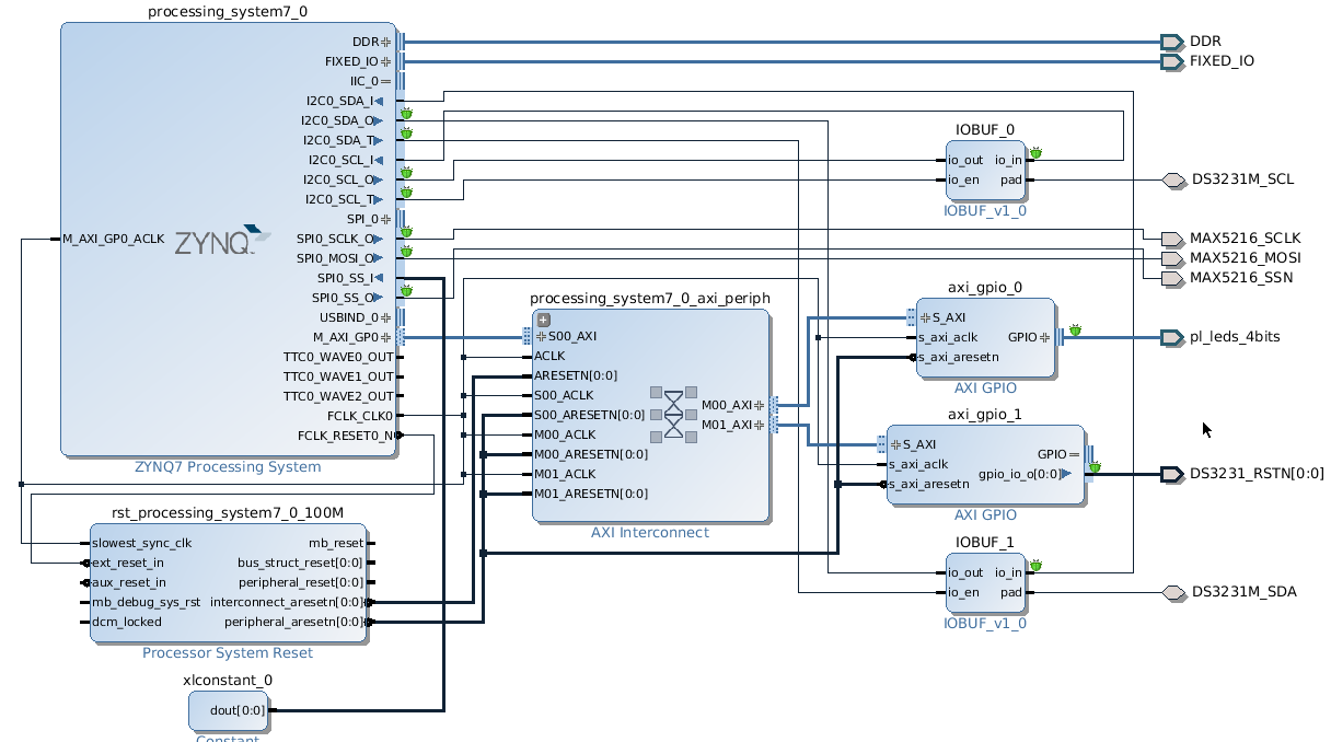
Note that I have also marked the pins for debug. This can be really useful for debugging your software using the embedded logic analyzer feature of Vivado.
Now synthesize the design and use the I/O Planner to place the outputs where you want on your FPGA. Generate a bitstream and export your design to SDK. These steps are covered in other tutorials, so I won’t go into details here.
Build PetaLinux
You need to create a PetaLinux project and extract the hardware description from your project SDK directory as discussed in tutorial 23. Before you build PetaLinux, though, you need to modify the device tree to create the appropriate device file for your SPI device. This step is critical: without it, Linux won’t create the SPI device file to control your device.
The first step after creating your project is to use petalinux-config to read the hardware description that you exported from Vivado.
petalinux-config --get-hw-description <path to project.sdk directory>
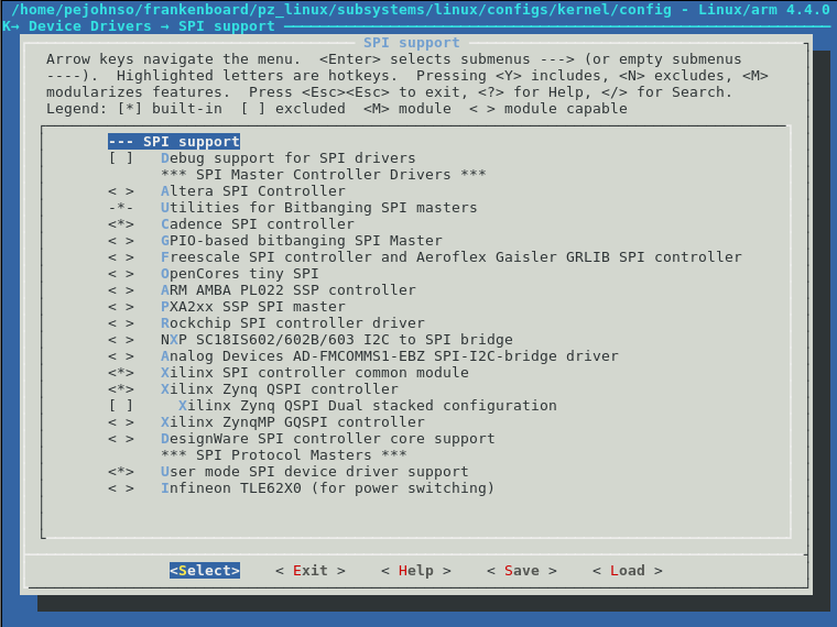
Then you need to enable SPI support for your kernel. To configure the kernel run the following command.
petalinux-config -c kernel
Navigate to Device Drivers->SPI support and make sure that Cadence SPI controller, Xilinx SPI controller command module, Xilinx Zynq QSPI controller, and User mode SPI device driver support are all enabled. If you fail to enable the User mode SPI support then the SPI device files will not be created.
Edit the file subsystems/linux/configs/device-tree/system-top.dts in your PetaLinux project directory, then add the following lines.
&spi0 {
  is-decoded-cs = <0>;
  num-cs = <1>;
  status = "okay";
  spidev@0x00 {
    compatible = "spidev";
    spi-max-frequency = <1000000>;
    reg = <0>;
  };
};
Now you can run petalinux-build and petalinux-package to build and package Linux.
Verifying the SPI interface
Once you boot your board, you should be able to see the SPI device file in the /dev directory.
root@pz-7015-2016-2:~# ls -l /dev/spidev*
crw-rw----    1 root     root      153,   0 Jan  1 00:00 /dev/spidev32766.0
You can compile the spidev_test program to exercise the SPI interface and view the results on the logic analyzer. To compile the spidev_test program, use the following command:
arm-xilinx-linux-gnueabi-gcc -o spidev_test /tools/xilinx/petalinux-v2016.2-final/components/linux-kernel/xlnx-4.4/Documentation/spi/spidev_test.c
Then copy the program to your board using ssh. Run the command, and if you use the embedded logic analyzer, you should see activity on the SPI interface.
root@pz-7015-2016-2:~# ./spidev_test -D /dev/spidev32766.0 --speed 10000000
spi mode: 0x0
bits per word: 8
max speed: 10000000 Hz (10000 KHz)
RX | 00 00 00 00 00 00 00 00 00 00 00 00 00 00 00 00 00 00 00 00 00 00 00 00 00 00 00 00 00 00 00 00  | ................................
In a future tutorial, I will cover the software side of controlling a SPI device in Linux.
Hi,
so I’ve been going through these tutorials and they have been very helpful!
However i have been given a PLL, (LMX2592evm) to interface with the zynq7000.
I don’t know how to go about it.
Will the block design in vivado be the same as given in this tutorial?
How can i get my fpga to control the LMX2592evm?
I’ll be very grateful to any help available!
Thanks.
You can use the SPI that is built-in to the PS on the ZYNQ chip like I show in tutorial 26 or you can use the bit-bang method I show in tutorial 24. Which SPI device you are using doesn’t really matter. The constraints and PS configuration will differ depending on how you are connecting the device to the board.
Hi – thanks for writing all of this up – it’s invaluable!
I’m trying to adapt the Xilinx SPI driver for use within a Zynq, but not using Petalinux. How can I get hold of a copy of system-top.dts? I tried to see your .c source from Tutorial 24 but the page is looking for login details. I have a .dts decompiled from a zedboard – I just want to compare it to yours.
The dts file is really Linux specific. If you aren’t using Linux then it really doesn’t apply. You can use the techniques described in tutorial 24 to bit-bang the SPI interface. If you only need low-speed control of a SPI device this can often be the simplest solution. Or you can look at the Xilinx baremetal drivers page http://www.wiki.xilinx.com/Baremetal+Drivers+and+Libraries for the Cadence SPI or the AXI SPI. Of course, sometimes it is just easier to read the spec on the SPI IP block and just program the registers.
I am using Linux, Xilinx Pulsar Linux in particular. I’ve since decompiled the .dtb that comes with the image into a .dts, so I don’t need system-top.dts anymore. Now I just need some insight into the MIO mapping syntax in the .dts, so that I can use all 3 chip selects on my only available SPI!
Hi,
Thanks for these helpful tutorial.
Every steps look fine except spi check. There is no spidev in dev directory.
When I power up the zedboard, ttyACM0 seems to be concerned, but when I configure gtkterm on this port, I can’t see anything.
I followed your tutorial 24 and 26, I’m clearly newbie on embedded OS etc.. but I followed your tutorial 24 and 26 and nothing seemed to go wrong.
Do you have any idea ?
Thanks
Sorry for the late response. Are you using the same version of Petalinux? There can be pretty large differences between versions and I have not run the tutorials with the latest versions.
Hi,
I started with your Tutorial 23, then I’m using petalinux 2015.4 with zedboard bsp 2015.4, but with Vivado 2017.4. However, I manage to open the serial connection, to boot (writing “boot” in the console) and to login with “root”.
Thanks for these tutorials, and your answers.
Hello,
I am using microzed board with linux os.I want to communiacte with an adc connected to SPI0 controller in the microzed board.Can I use the spidev_test.c program to verify whether the device is responding and is it necessary to edit .dts file?
Thanks in advance……..
You need to edit the dots file to tell the Linux build process about your SPI device. Without the entry in its file Linux won’t have a spider device file in dev to talk to your device.
Let me know if you have more questions.
Hello,
Thanks a lot for wonderfull sharings.
At your last sentence you are saying, “In a future tutorial, I will cover the software side of controlling a SPI device in Linux.”
Is there any progress about this tutorial?
Regards
Saban,
I should probably do that. Of course life has intervened since that statement was written and I have not gotten to it. I have however controlled a lot of SPI devices since then from Linux. If you have a particular question, or would like to see some example code dealing with a SPI device, let me know and I will try to help.
-Pete
Hi Pete,
Thank you for your reply.
I’m already controlling an ADC by using Petalinux spi_test driver as you described in your article.
My next step is: configuring a lot of devices over SPI.
Additional ADC, DAC, Flash..
My ZYNQ need to be connected a lot of cards.
It will also connect to a sub(low cost FPGA), and this fpga will configure some hardwares over SPI.
It means ZYNQ can configure some devices directly over SPI and also it connects to low cost FPGA and this FPGA can configure hardwares on it.
Have you ever implemented a design like that?
Whay is your advice?
Regards,
Saban
Saban,
Yes, I have implemented many systems like that. How are you connecting the ZYNQ to the other FPGA? How you do this will depend on a couple of factors. First, how fast does the interface need to run? Both in terms of throughput and latency. Do you have access to transceivers for the interface? If so then you can use a Xilinx chip to chip bridge. You can even use one if you don’t have those but only have an AXI streaming interface. Either a parallel interface between the chips, or you could make a serializer which takes the AXI streaming interface and maps it to a serial stream. Or you could use a SPI interface between the two FPGAs.
Another route is that you can have a SPI register on the remote FPGA which controls a MUX that lets the SPI interface there, in turn, drive the SPI master interface on the remote FPGA. Essentially the register would serve as the source for the remote chip selects. I have done this when the remote FPGA is just a simple CPLD which is there pretty much to multiplex multiple SPI devices.
Let me know if you have more questions. Feel free to send me an email on the topic since it is straying outside the scope of the tutorial.
Thanks,
-Pete
Hi Pete,
Thanks for such nice tutorials. I am new to the world of Zynq and the first task I need to handle is the SPI interface on petalinux.
What if I want to use the MIO pins and not the EMIOs? I have used MIO pins to run SPI on zedboard without the petalinux.
Also if I am using SPI1 instead of SPI0, will be there any change in the .dts file ? will the &spi0 become &spi1 in my case? or any other modification? I have no idea 🙂
Regards
Mohsin
Mohsin,
To use the MIO pins you just need to configure the IO for the ZYNQ in the block design. If you change which SPI device you are using then the device tree also needs to change. And you need to make sure to enable the usermode SPI driver when you configure Petalinux. Make sure that once you boot you see the /dev/spidev* device files.
-Pete
Hi Pete,
Thank you so much for this tutorial. I´m using the MIO Pins for the SPI. I already found the spidev file in the dev directory. But when i compiled the spidev_test i could see only this:
spi mode: 0x0
bits per word: 8
max speed: 10000000 Hz (10000 KHz)
Do you know what could be the reason for not seeing the RX 00 00 00 00 ?
Thank you!!
-Imen
Imen,
Unfortunately with the MIO pins you can’t see them on an ILA. Can you check with a scope on the board to see if the signals are changing? Are you sure you ran the spidev command with the correct arguments? Make sure you are using the correct device file too.
-Pete
Hi Pete,
Thanks for detailed tutorial.
I am using zc702 evaluation board and vivado 2019.1,petalinux 2019.1.
I am trying to interface zc702 board to interface with adc(ad9434) via spi bus.
I am using EMIO pins itself for spi.
I already found the spidev file in the dev directory. But when i compiled the spidev_test i could see only this:
spi mode: 0x0
bits per word: 8
max speed: 10000000 Hz (10000 KHz)
Do you know what could be the reason for not seeing the RX 00 00 00 00 ?
Could please help in this?
Venkat,
Sorry to take so long to respond. Vacations and California fires have been delaying things.
Have you connected an internal logic analyzer to the pins you are using on the EMIO interface? You can also connect it to the AXI bus to see the memory transactions from the ZYNQ.
Let me know if you have made any progress. And if you haven’t what you see on the ILA.
-Pete
Hi Pete,
I’m working on enabling SPI device (PL block) on ZCU104 board, followed the steps mentioned in this article (tutorial 26) to enable SPI DEV in kernel config and add spidev in system-user.dtsi , rebuilt device-tree / kernel ..
Yet to see the SPI device under device nodes “/dev/ “..
Could you please advise as to what am I doing wrong …
Sorry for the late response. Make sure you have properly enabled the SPI drivers in the kernel. Make sure that the SPI device is in the compiled device tree for the kernel. You may need to start over from a clean directory. Petalinux is not all that great at rebuilding everything it may need to if some source files change.
Hello,
I am trying to interface with an OmniVision OG02B10 camera with the Zynq. I want to be able to retrieve images from the camera using commands issued by the SoC. I also went through your tutorials 24 and 26. Now I am confused about interfacing with the camera using an i2c core in Vivado? Is it possible to interface the camera by directly defining an IP in Vivado and then use the device drivers (i2c) from Petalinux?
Yes, you can either use one of the two I2C interfaces in the processor subsystem or you can instantiate the I2C AXI controller in the PL. The PS controllers are the simplest to use. With the PL controllers, you need to be sure to enable the Xilinx I2C driver in the kernel.
But I believe that the camera uses a MIPI interface. There is a Xilinx IP for MIPI but I have never used it. What board are you planning to use?
thanks for the reply. In our camera module, we have designed for MIPI interface. board used is Zedboard which supports FMC card.
Even though your I2C interface is going across FMC you can still use the I2C controller in the PS. Just set the interface to EMIO and then connect the SCL and SDA pins in the PL design. They are just handled like normal bidirectional signals. There is an input, output, and output enable for SDA and SCL. You connect those to an IOBUF and then to the package pins you want to use.
When you build a Linux image be sure to enable the I2C tools and you can use i2cdetect, i2cset, and i2cget to see the I2C device and interface with it.
Hello Professor,
I would like to appreciate your work for providing such wonderful tutorials. (This is really helpful for beginners like me).
I would like to use similar approach as you described in the tutorial. My slave device is MAX2771 RF front end. My master device is Zed Board. I have to configure the registers of the slave (MAX2771) using SPI protocol.
I found that my slave has 3 wires for SPI communication. (common wire for MISO and MOSI). So I wanted to ask you that how should I use 4 wire SPI in master to communicate with 3 wire SPI in slave.
Also, could you please suggest me if have to use PS SPI or AXI QUAD SPI. In case you have any reference for this task then it would be very kind of you if you could provide me.
Thanks and regards.
Hi Sir!
I am new to the world of embedded systems and ZYNQ. I’m working on ADC AD7616 and I’ve to enable SPI interface for the AD7616 to communicate with the IP in vivado. Codes are available on GitHub. But they provided the three SPI interface, axi_spi_engine, axi_spi_engine_execution, axi_spi_engine_offload and axi_spi_interconnect. But I don’t know the sequence how to connect them and make block diagram. Can you please help me to tell how to tackle them and how to make the connections.
I’ll be really very thankful as it’s related to my final year project and stuck badly.
i am using custom board and in that spi is connected to tmp123(temperature sensor),
i would like to ask you how to do device tree changes in system_user.dtsi to register my device and if i am enabled the lm70 driver from petalinux-linux -c kernel it giving taint warning petalinux-2020.1
kindly help me out.
Hi. I wrote a software to control the spi device in petalinux but when I run it, there is no read data available in the rx buffer (I am using ioctl to read and write). When I checked the signal with an oscilloscope, I found only the clock goes through from the fpga to the spi device. What could be the issue here?
Sorry for the late response. I’ve been on vacation most of the month.
Anyway, You can use either the PS SPI or the AXI QUAD SPI. My preference is to usually use the PS SPI since it doesn’t take any logic in the fabric and is well supported by Petalinux and the Xilinx bare metal libraries. As for the single data pin, just connect it to the MOSI and the MISO output and input of the SPI module. At the software level you will need to interpret the data correctly.
I hope that helps.
Thanks,
-Pete
I am unfamiliar with what you are referring to on GitHub. You can just use the SPI controller that is built into the ZYNQ PS. The tutorial covers how to do that. Let me know if there is a reason you need to use some other IP.
Thanks,
-Pete
I don’t have any experience with the lm70 driver for the tmp123 sensor, so I’m afraid I can’t offer much advice here. But there must be an example device tree entry that you can emulate with your system.
Thanks,
-Pete
Sounds like you have a problem with your pin mappings. Connect an internal logic analyzer (mark for debug) the signals in the FPGA and look at the transactions there. They should match the oscilloscope. If they do not then look for an issue with the pin mapping. If they do match what you see on the scope then you may not be controlling the SPI controller correctly with your software. You should see the clock, chip select, and mosi signals wiggle when you run a transaction.
Let me know if you figure it out.
-Pete
Hi Pete,
I am using zcu102 eva board. I configured the PS SPI0 through EMIO interface and re-route the clk, cs, MOSI, and MISO to some on-board leds so I can probe the SPI signals by using the oscilloscope. When I ran the spidev_test, I found the data of Rx is always the same as data transmitted through MOSI. I probed MOSI line. The waveform shows the exact data being sent. CLK and CS also show correctly. The MISO shows 0x00 on the oscilloscope as the expected. However, the data received by the Rx buffer of spidev_test shows the same as Tx instead of 0x00. If manually pull down the MOSI line, then the Rx buffer has 0x00. I did the same thing for MISO, there is no impact to the Rx buffer. It seems the transmitted data is looping back. Can you please provide some advises?
Thank you,
Ron
Hi Sir!
I’m configuring ADC with ZYNQ. I’m designed my system on Vivado 2020.1 (Windows). I want to control the adc and want to read and write the registers of ADC for that I’m using SPI0 and SPI1 of zynq. First please tell me either if I need both the SPI for it or not? Secondly when I try to read the registers that always send back 0x0. Then, I dig out the problem and noticed that SCLK of SPI remain high and not toggling (not generating clock pattern to read or write). I don’t know what’s the problem is. The CNVST and BUSY are working properly as per data sheet of ADC but SCLK remain always high.
Please suggest me any solution as I’m stuck on this since few days. Is there any other way to contact you so that I can share scope shots with you as well.
I’ll be really very thankful to you.
Regards
@Sampreet Sarkar
Have u been able to run the camera on zedboard. I was also working on same project.
Hi Pete.
Can you please help me to bring up SPI device on zynq RFSOC.
1. I exactly followed your tutorial, now i can see the spi device file under the /dev directory.
/dev/spi0.0
2. In my case chip select pin is not working properly, that means there is no sync between
CS and clock when i tried to send the data.
3. The CS duration is 30 ms and the gap between clock and CS is 18 ms.
4. please let me, what is the issue.
5. We are using vivado and petalinux with 2020.2 version.
6. Board : zynq MPSOC zcu106 evm board.
Thanks and regards,
Sunil AP
I am using zynqMP and petalinux version 2021.1, where do i need to change?
Not much. Pretty much all of this applies to zynqMP. You will need to compile spidev_test for the 64-bit architecture instead of 32, but that’s about it.
Hi Pete,
I am trying to initiate the SPI communication from the PS and routed it to my pmod pins through the EMIO. I am using petalinux version 2021.1 with the same version of vivado. SInce petalinux has changed the way it works since the version you created the tutorial, offcourse there were minor modifications to be made. One of them was to add the device tree changes to system-user.dtsi in proj-spec/meta-user/recipes-bsp/device-tree/device-tree/files. After making these changes and enabling the required drivers i could succesfully build the project. However when i moved all the files to sd card and booted my device i could not find spidev1.0 in my devices.
I was wondering if the device would appear only when i connect the spi interface with the slave device. I also noted the pcw.dtsi file after the build and i could only see the part of the code below has been added.
&spi0 {
is-decoded-cs = ;
num-cs = ;
status = “okay”;
};
FPGA board used – Kria KV260
Any insights would be helpful in the solution direction.
With Regards,
Vishnu
Vishnu,
You need to turn on the user-mode SPI driver with
CONFIG_SPI_SPIDEV=y
in a Petalinux config file. You can also do this through menuconfig.
Your spidev entry should look something like this
&spi0 {
is-decoded-cs = <1>;
num-cs = <4>;
status = “okay”;
spidev@0 {
compatible = “spidev”;
spi-max-frequency = <50000000>;
reg = <0>;
};
};
You should also get a bunch of messages at boot that look like some terrible error. But it’s just the driver writer being pedantic and complaining that nobody should be using user mode SPI devices directly. Let me know what you discover.
-Pete
Just curious why in the SPI DTS file you are setting spi-max-frequency to 1 Mhz and not 10Mhz as you are setting during the transfer. So the kernel mode driver is not capping the freq to 1Mhz?
Hi I have a few questions – in your DTB, you provided 1Mhz for spi-max-frequency in DTB but you are getting 10Mhz, does the driver then change the clock divider internally? The default clock is from i/o clock of 166.6666667 Mhz which is where SPI clock comes from after divider. I am looking for the spi.Config_reg base address to be able to do this myself but all I am finding is this config reg is only associated with QSPI.
Thanks
Ratin
I think that’s probably a typo in the spidev command. I’m not sure if the device can communicate at that speed.
Hi Pete,
Thanks a lot for such a nice article.
Currently in one of my project, i am trying to enable the SPI1 interface by using the device tree configurations but somehow i am not able to see it in the /sys/bus/spi/devices part.
Here is the configuration in the system.dtsi file :
spi1 {
is-decoded-cs = ;
num-cs = ;
status = “okay”;
spidev@0x00 {
compatible = “spidev”;
spi-max-frequency = ;
reg = ;
};
};
Here is the final system.dts file which gets generated and here we have the following :
spi@ff040000 {
compatible = “cdns,spi-r1p6”;
status = “okay”;
interrupt-parent = ;
interrupts = ;
reg = ;
clock-names = “ref_clk\0pclk”;
#address-cells = ;
#size-cells = ;
power-domains = ;
clocks = ;
is-decoded-cs = ;
num-cs = ;
phandle = ;
};
This is aliases section….
aliases {
ethernet0 = “/axi/ethernet@ff0b0000”;
ethernet1 = “/axi/ethernet@ff0c0000”;
ethernet2 = “/axi/ethernet@ff0e0000”;
i2c0 = “/axi/i2c@ff020000”;
i2c1 = “/axi/i2c@ff030000”;
serial0 = “/axi/serial@ff000000”;
spi0 = “/axi/spi@ff0f0000”;
spi1 = “/axi/spi@ff040000”;
spi2 = “/axi/spi@ff050000”;
};
I have two doubts in this regard,
1. Is the device tree configuration approach and modifications what we have done is correcr ?
2. Secondly the cadence device drivers, is it because of this the /sys/bus/spi/devices are not seen ?. Becuase i could see the info in another path which is /sys/devices/platform/axi/ff040000.spi here
Any inputs from you on this would be really helpful
Hello Pete,
I am trying to interface SPI ADC(MCP3208) with zed board using qspi ip(standard spi mode). I have done synthesis and assigned the corresponding pins but I am unable to see the clock and SS line go on oscilloscope .I am not able to see the adc data on the terminal. I would be grateful if you could provide me any guidance in this.
Thank you
Sorry for the late response. Are you seeing the spidev device file in /dev? If you run spidev_test and point it at the spidev device file you should see something.
One thing I find helpful is to install the device tree compiler package (dtc). Then you can run “dtc -I dtb -O dts system.dtb” Then you can see the source file for what was actually created. Probably you attached your device tree information to the wrong node in the device tree. Seeing the decompiled binary will show you where.