In this tutorial, we’re going to add some improvements to the I2S receiver we started working on in the last tutorial.
Audio Sample Size
The receiver in the previous tutorial has a sample size of 32 bits. What if the I2S master sends data with fewer bits? The previous design would work, but the data would reside in the lesser significant bits of the output. For example, if a 16-bit sample size were used, then the data would reside in the lower two bytes of the output word. Even worse, we never clear the shift register, so on the next sample the upper bits would have data in them.
In general, if you have a system with 16 bits of data and another with 20 bits of data, the second system is adding precision to the sample. Those extra bits are extra low significant bits. In general, it is desirable to make the first bit of data received on a sample the most significant bit of the output word. Output bits which don’t get set by the incoming data stream should just be set to zero. If you do this, you can just pass data around internally as 32 bits, and you don’t need to care how many bits are really transmitted by the master. In fact, the master could really transmit a different number of bits on every sample. In fact, our next test will do just that.
Block Diagram
Here is a block diagram for our new receiver. This comes pretty much straight from the I2S standard. I have made some changes to make it a little easier to translate into Verilog:
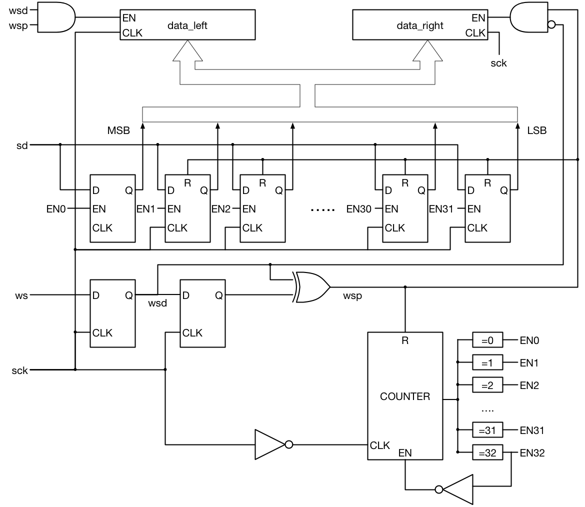
I2S receiver block diagram
Changes from the previous design
The shift register has been changed from the previous design. In fact, it is really no longer a shift register. Instead the SD input goes to every bit in the register. An enable signal controls when the SD bit is written to the register. This enable signal comes from a counter which counts from zero to 32. Once the counter hits 32, it can no longer enable any flip-flop and it waits for the wsp signal to clear it. This allows the master to send more than 32 bits of data, and the receive will ignore the extra bits.
Also, you can see that the wsp signal also resets 31 or the 32 data bits. This allows the master to send fewer than 32 bits of data and the low bits of the receive data register will remain zero.
Go ahead and implement your design now. Note that all the reset signals are synchronous.
Files
Here is the test for the i2s_receiver2 module that you will write. It sends samples of 3 to 40 bits and the number changes with every sample. Your design needs to properly handle short or long samples. In the next section we will discuss improvements that you can make to your module.
In the next section we discuss your code and some thoughts on doing a better implementation.
Hi Pete, it appears the test file i2s_receive2_test.v link is broken or the file is not in place.
Thanks for the catch. It should be fixed now.
Really Useful Tutorial . Thank you 🙂
Hey the common_test_util.v is locked under username and password, is it possible to still access this?
Hi Pete, it seems like the link for the common_test_util.v isn’t working
Should be working now. Sorry for the delay.