Remote debugging with the Arrow SoCkit board

Background

My FPGA builds are done on a server in the datacenter, which is helpful for a number of reasons, not the least of which is that it takes a lot of CPU, and the server has plenty of CPU power. However, it’s a pain to transfer the design files over to a local machine for programming and debugging. Here are instructions that you can use to run just a JTAG server on the lab machine, and connect to from the server machine.

Lab Machine

Install

You should install the Quartus II tools on the lab machine. There’s got to be a download for only the programming tools, but I haven’t found it yet. Download and install only the minimal amount. The machine needs to run the port mapper and xinetd. You may need to install those with yum or whatever other package manager your distribution requires.

Starting the Server

In the following, I assume that the environment variable $qII points to your Quartus II install directory.

You need to make sure that a file /etc/jtagd/jtagd.conf exists and has the following line in it:

Password = “mysecret”

Without that, the jtag daemon will not listen for remote machines.

First check that the JTAG software can see the board. Run the following command and verify that you get the correct output…

[pete@localhost ~]$ $qII/quartus/bin/jtagconfig
 1) CV SoCKit [1-1]
 02D020DD 5CSEBA6(.|ES)/5CSEMA6/..
 4BA00477 SOCVHPS

Then, run the following to start the server. You need to do this as root:

[pete@localhost ~]$ sudo $qII/quartus/bin/jtagd
[pete@localhost ~]$ sudo $qII/quartus/bin/jtagconfig --enableremote mysecret

Remote Machine

On your remote machine you should start up Quartus II, and:

Select Tools->Programmer. This will start the programmer window.
You should then click the Hardware Setup… button.
Click on the JTAG Settings tab.
Click the Add Server… button.
Enter the IP address of your server. Enter the password, greywolf.
The Hardware Setup window should indicate the server IP address and the connection status should be OK.
Click the Close button.
You should then see the IP address of the lab machine to the right of the Hardware Setup… button.

You should now be able to use the JTAG device from the remote machine.

Pro Tips

If your lab machine doesn’t have a public IP address– for instance, because it is a VM using NAT running on a host with a VPN connection to your server– you will need to set up an SSH tunnel to the lab machine.

The JTAG server runs on port 1309. You can use ssh to tunnel the connection.

From your VPN machine ssh to the remote machine with the following command:

[pete@localhost ~]$ ssh -L 1309:192.168.1.2:1309 user@myserver.mydomain.com

In this example, your guest machine has an IP address of 192.168.1.2, and the remote server is myserver.mydomain.com.

Then, you would use your VPN machine IP address as the address of the lab machine when connecting to the JTAG server.


Timing Diagrams with WordPress

I saw a post yesterday on Hackaday about using a program called Wavedrom to edit timing diagrams on web pages. It looks like a great tool, but I have a couple of issues with it.

First, I’m confused about the command line version of the tool. It exists, but there seems to be some issue with using it on Mac OS. I haven’t tried it on Linux yet, but most of my work is done on both, especially documentation, so I need to get that figured out.

The second really big gotcha is that it doesn’t work with Internet Explorer 9 and earlier. That is a big one. Even though I personally never use IE, a lot of my readers do.

Anyway, with those caveats in mind, I did some work to try to integrate Wavedrom with WordPress. Here is an example waveform:

Apologies if you use IE since you can’t see the waveform. You can check it out in Firefox or Chrome, though.

You can see the full tutorial for WaveDrom here for more details. But for the example above, the code embedded in this page looks like this:

<script type="WaveDrom">
{ signal : [
{ name: "clk", wave: "p......" },
{ name: "bus", wave: "x.34.5x", data: "head body tail" },
{ name: "wire", wave: "0.1..0." },
]}
</script>

I created a very simple plugin for WordPress which adds the right stuff to the HTML header for these pages. I will probably work on it a bit further if I can figure out how to support IE. If I can’t do that, maybe I can get the command line version working, and use it for PNG or SVG images at least.

Putting New Files in the Right Place: The Vivado Edition

Vivado has the ability to create and manage your own IP, which is a good thing. But there are some real gotchas when doing something like this, the first being that it doesn’t seem to place HDL files in the correct locations.

I have been running some FPGA workshops using the IP Packager in Vivado and having been having a lot of problems when creating new files in the IP component. Here’s an example:

From a Vivado project select Tools→Create and Package IP… Click Next, select Create a new AXI4 peripheral, click Next, just use the defaults for the next page, click Next again, use the defaults for the AXI information and click Next again, select Edit IP, then click Finish.

This will put in an IP Packager project. Edit the top level file myip_v1_0. I’m using Verilog but it works the same for VHDL. Instantiate a new dummy module at the bottom of the file:

// Add user logic here
dummy dummy (.clk(s00_axi_aclk));
// User logic ends

files_fig1Save the file and look at the design sources. You will see that there is now a new undefined module in the design called dummy. It should look like the figure to the right:

Now, we would like to create the new module. So we go to File→Add Sources… and create the new source file. Select Add or create design sources and click Next. Click Create File …, type the file name dummy and click OK. Click Finish. When the Define Module dialog pops up, just click OK. Click Yes to the dialog saying you haven’t changed anything. You now have a file defined for your dummy module.

files_fig2Ready to package that IP? Go to the Package IP tab in the Project Manager window. Then, select File Groups in the Packaging Steps window. You should see a window like the figure on the right.

Now click on the Merge changes from File Groups Wizard link. You will then get a link saying 2 warnings. Click on that, and you will see two warnings about your dummy.v file being on a path which is not relative to your IP root directory. What has happened is that Vivado placed the new file outside the IP component. If you go ahead and package your IP, you cannot use the packaged IP because it will be missing this file. Seems like a Vivado (2014.4) bug to me.

So how should we fix this? I don’t know how to move files in Vivado, but we can create the file in a different location when we make the new file. To do that, first delete the dummy file and remove it from disk. Just select the file, then right-click and select Remove File from Project. Select the checkbox to also delete it from disk and click OK.

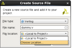
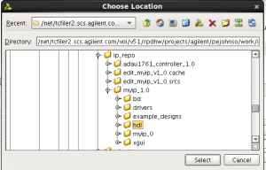
files_fig3Now go to Add Sources again, and after clicking Create File…, specify the file name dummy.v, then select a new file location. files_fig4Navigate to your ip_repo area and into myip_1_0. Select the hdl directory, and click Select. Then click OK and then Finish to create the file. This will place the file in the proper location in the IP repository.

When you merge your changes in the File Groups step, you should not get any warnings. You can then package your IP and use it in your designs.

Hopefully this will be fixed in the next release of Vivado.

Remote JTAG with Vivado

My FPGA development computer is a server in a datacenter. It stores lots of memory and CPU, but it’s impossible to connect it directly to my development boards. ISE has always supported remote JTAG servers, but the implementation has always been spotty. In some releases it has difficulty with some versions of Linux. With Vivado, things are much improved.

If your lab machine is on the same network as your development machine, simply start the hw_server program in the Vivado bin directory and open a target from the development machine Vivado window. Just specify a remote server host name and use the default port 3121. It couldn’t be simpler.

If your lab machine is behind a firewall, you may need to use SSH to tunnel the traffic through. First, make sure the hardware manager is not running on your development machine. From the lab machine, ssh into the development machine with the following command:

ssh -R 3121:localhost:3121 development.my.com

This will create an SSH tunnel from your lab machine to your development machine. If you get a warning saying that SSH can’t bind to the required port it means you are still running a local JTAG server on your development machine. Assuming all went well you should be logged in to your development machine from the lab machine. You can then open the target in the hardware manager in Vivado but tell it to connect to a local machine. Vivido will see a server already running on port 3121 (through your SSH tunnel), so it won’t try to start a new one.

If your lab machine is running Windows then you can use the open source PuTTY program to make the tunnel. If your development machine is running Windows, then you need to install an SSH server on the machine. That’s beyond the scope of this post.

A Verilog Preprocessor

A long time ago…

When I used to work at Silicon Engineering in the nineties, I wrote a Verilog preprocessor using Perl. Verilog ’95 is pretty limited in what it can do, so we used this preprocessor on our projects to enhance our Verilog code. Back in the Verilog ’95 days, we used to write every RTL file as a preprocessor file and used GNU Make to convert it into pure Verilog. What with Verilog 2005 and System Verilog, these days I only use this preprocessor when necessary. But that’s still pretty often.

The trick

The cool thing about this preprocessor is that it does very little of the work on its own. It can be used in place of the standard Verilog preprocessor– which is well and good if you need that type of thing, but it’s still pretty limited. After all, you already have something that does that. This preprocessor’s neat trick is that you can embed Perl code inside your Verilog code. What the preprocessor does, essentially, is it converts the input code into a perl program which, when run, prints the input code. Now, by itself that is kind of boring. However the preprocessor allows you to use special comments to drop out of this mode and embed Perl code.

A simple example

One simple example of what you can do is to build a table to use in your Verilog module. In my CORDIC module, I needed a table of arctan values. This table is static and doesn’t ever need to change. All I needed was one entry in the table for each pipeline stage in the CORDIC. The table takes the pipeline stage number as input and returns a 64-bit value as the result. I implemented this as a function which is basically just a big case statement. You can see the special comment is wrapped in a /*@ and @*/ pair. I chose these because they are real Verilog comments so they won’t mess up editors that know how to edit Verilog (like Emacs). Once you drop into Perl mode, anything that your Perl code writes to standard output will appear in the preprocessor output. Here is the input to the preprocessor:

   function [63:0] k_table;
      input [5:0] index;
      begin
	 case(index)
/*@
  $k = 1;
  for my $i (0..63)
    {
      $k *= cos(atan2(1,2**$i));
      printf "%8d: k_table = 64'd%s; // %.20e\n",$i,int($k*2**64+.5),$k;
    }
 @*/
	   default: k_table = 0;
	 endcase
      end
   endfunction

Interpolation

Code enclosed within the /*@ and @*/ pairs, or prefixed with the //@ comment, is just copied into the output Perl program. Other lines are just printed by the Perl program, which means you can use Perl string interpolation on those lines. Here’s a rather contrived example:

//@ my $reset_style = " or negedge clk";
always @(posedge clk $reset_style)
  q <= d;

In this example, the Perl reset_style variable is used in the verilog code without needing to drop into the more cumbersome comment syntax. This can help make your code a lot more readable. I have a library that I commonly use which defines a bunch of variables. These variables match the Verilog system tasks and functions that begin with a dollar sign ($). This way, you can say $display and the preprocessor will expand the Perl variable display (which, by the way, conveniently has the value $display.)

Other Possibilities

I also write a lot of structured documentation for my designs using XML. By using the XML::LibXML library I can read the XML documentation from my Verilog code and parse that for information that drives the RTL code generation. So I can document registers, instruction sets, interrupts, or other types of information, and then that do generate my verily code.

Useful Links

Look for more posts using this technique soon.