Getting the Log Base 2 Algorithm to Synthesize

My last post introduced an algorithm for finding the log base 2 of a fixed point number. However, it had a gotcha. It had to use some floating point functions to initialize a table, and even though it is not synthesizing floating point, ISE, Vivado, and Quartus II all refuse to synthesize the design. What should we do?

Perl Preprocessor to the Rescue

In an older blog post, I discuss a Verilog Preprocessor that I wrote years ago. In the old days of Verilog ’95, preprocessors like this were practically required. The language was missing lots of features that made external solutions necessary,  but got largely fixed with Verilog 2001 and Verilog 2005. Now with Systemverilog, things are even better. However, sometimes tools don’t support all of the language features. In the last blog post, we discovered that the FPGA synthesis tools can’t handle the floating point functions used in the ROM initialization code.

Computing the lookup table in Perl

What we’ll do is write the ROM initialization code in Perl and use the preprocessor to generate the table before the synthesis tool sees it.

The code which gives the synthesis tools fits is this:

  function real rlog2;
    input real x;
    begin
      rlog2 = $ln(x)/$ln(2);
    end
  endfunction

  reg [out_frac-1:0] lut[(1<<lut_precision)-1:0];
  integer i;
  initial
    begin : init_lut
      lut[0] = 0;
      for (i=1; i<1<<lut_precision; i=i+1)
        lut[i] = $rtoi(rlog2(1.0+$itor(i)/$itor(1<<lut_precision))*$itor(1<<out_frac)+0.5);
    end

We can essentially turn this code into Perl and embed it, so that the preprocessor will be able to generate it for us. Remember, the Perl code goes inside special Verilog comments.

First, we’re going to need to define some parameter values in Perl and their counterparts in Verilog. These define the maximum allowable depth and width of the lookup table.

  //@ my $max_lut_precision = 12;
  localparam max_lut_precision = $max_lut_precision;
  //@ my $max_lut_frac = 27;
  localparam max_lut_frac = $max_lut_frac;

Here is the Perl code to compute the lookup table values:

  /*@
   sub compute_lut_value {
     my $i = shift;
     return log(1.0+$i/(1<<$lut_precision))*(1<<$lut_frac)/log(2.0);
   }
   @*/

Then, we’ll embed the lookup table inside a Verilog function.

  function [max_lut_frac-1:0] full_lut_table;
    input integer i;
    begin
      case (i)
	//@ for my $i (0..(1<<$max_lut_precision)-1) {
	//@ my $h = sprintf("${max_lut_frac}'h%x",int(compute_lut_value($i)+0.5));
	$i: full_lut_table = $h;
	//@ }
      endcase
    end
  endfunction

We’re also going to parallel the Perl code with a pure Verilog function, just like our local parameters.

  function [out_frac-1:0] compute_lut_value;
    input integer i;
    begin
      compute_lut_value = $rtoi(rlog2(1.0+$itor(i)/$itor(1<<lut_precision))*$itor(1<<out_frac)+0.5);
    end
  endfunction

But how do you parameterize it?

There happens to be one gotcha when working with preprocessors: you really don’t want to use them. Back in the Verilog ’95 days, my colleagues and I just used the preprocessor for every Verilog file. All of our parameterization was done there. We used a GNU Make flow, and it built all the Verilog files for us automatically. But with the advent of Verilog 2001 and SystemVerilog, a lot of things that we used the preprocessor for could be done within the language– and much better, too. One of the crufty things about using the preprocessor was that you needed to embed the parameter values in the module names. Otherwise, you would have module name conflicts for different modules with different parameter values. In this case, we actually want the preprocessor to generate a parameterized Verilog module. We still want to use the normal Verilog parameter mechanism to control the width and depth of the lookup table.

To do this, we must generate a maximal table in the preprocessor, and then cut from that table, using Verilog, a subtable that has the desired width and depth based on our Verilog parameter values.

Here is the code to do that. If the values of the depth and width (precision and fractional width) exceed the maximal Perl values, then we just use the pure Verilog implementation and the code will not be synthesizable, but it will still work in simulation, at least. If the parameter values are “in bounds” for the preprocessor-computed lookup table, then we’re going to go ahead and cut our actual table from the Perl generated lookup table, and the design will be synthesizable.

  reg [out_frac-1:0] lut[(1<<lut_precision)-1:0];
  integer i;
  generate
    // If the parameters are outside the bounds of the static lookup table then
    // compute the lookup table dynamically. This will not be synthesizable however
    // by most tools.
    if (lut_precision > max_lut_precision || out_frac > max_lut_frac)
      initial
	begin : init_lut_non_synth
	  lut[0] = 0;
	  for (i=1; i<1<<lut_precision; i=i+1)
	    begin
	      lut[i] = compute_lut_value(i);
	    end
	end
    else
      // The parameters are within bounds so we can use the precomputed table
      // and synthesize the design.
      initial
	begin : init_lut_synth
	  for (i=0; i<1<<lut_precision; i=i+1)
	    begin : loop
	      reg [max_lut_frac-1:0] table_value;
	      table_value = full_lut_table(i<<(max_lut_precision-lut_precision));
	      lut[i] = table_value[max_lut_frac-1:max_lut_frac-out_frac];
	    end
	end
  endgenerate

We can then finish off the design, just like in Computing the Logarithm Base 2

Conclusion

This may be a lot to take in. But the gist is that you build a table using the Perl preprocessor, which is large enough to use for all parameter values. Then in Verilog, you use the actual parameter values to cut out the portion of the pre-computed table that you need. This cutting out can be done during the elaboration or initialization stages of the synthesis. Of course, our job would be much easier if the synthesis tool developers got it into their heads that using floating point and math during elaboration or initialization does not necessitate synthesizing floating point logic.

If anyone knows of a software floating point library written purely in Verilog, please let me know. We could then use that to trick the synthesis tools into doing what we want.

Oh, and here’s a link to the complete file.

Detecting the rising edge of a short pulse

A reader is going through my ZedBoard tutorial and had some questions about detecting the rising edge of a pulse. The tutorial in question is using a ZedBoard to make a stopwatch. Kind of overkill in terms of hardware, but you have to start somewhere when you’re learning to code.

TRAN MINHHAI’s question asked: what do you do when the rising edge might just be a pulse, and the pulse might last less than a single clock cycle? The answer is to use a flip-flop with the input signal going to an asynchronous set input. The data input is just zero, and the clock signal is the one we are synchronizing to.

Here is the code:


`timescale 1ns/1ns
module edge_detect
  (
   input clk,
   input btnl,
   output btnl_rise
   );

  reg btnl_held = 0;
  always @(posedge clk or posedge btnl)
    if (btnl)
      btnl_held <= 1;
    else
      btnl_held <= 0;

  reg [1:0] btnl_shift = 0;
  always @(posedge clk)
    btnl_shift <= {btnl_shift,btnl_held};
  
  assign btnl_rise = btnl_shift == 2'b01;
endmodule

I also wrote a little test to go with it. Notice how short little pulses can come anywhere with respect to the clock edge:


`timescale 1ns/1ns
module edge_detect_test;

  reg clk = 0;
  always #10 clk = ~clk;

  reg btnl = 0;

  wire btnl_rise;

  edge_detect edge_detect(clk,btnl,btnl_rise);

  initial
    begin
      $dumpvars(0);
      
      @(posedge clk)
	btnl <= 1;
      repeat (10) @(posedge clk);
      btnl <= 0;
      repeat (4) @(posedge clk);
      #10 btnl <= 1;
      #1 btnl <= 0;
      repeat (4) @(posedge clk);
      #19 btnl <= 1;
      #1 btnl <= 0;
      repeat (4) @(posedge clk);
      #20 btnl <= 1;
      #1 btnl <= 0;
      repeat (4) @(posedge clk);
      $finish;
    end
endmodule

The long pulse case

In the case of a long pulse, the design works just like it would without the asynchronous set flip-flop. Here’s a timing diagram:

The short pulse case

But if there is a short pulse, the asynchronous set flip-flop holds the input value until there is a clock edge.

If the pulse appears in the middle of the clock cycle, then the timing diagram looks like this:

If the pulse appears right before the clock edge, then the timing diagram looks like this:

Now you know how to synchronize the rising edge of a pulse even if you have a slow clock.

Computing the Logarithm Base 2

Algorithm

Computing the log base 2 of a whole number is easy: just use a priority encoder. But what about a fixed point number? That sounds a lot harder. But, like many things, there’s a trick to make things easier.

Consider the following equation:

\log_2{x} = \log_2 (2^n \cdot 2^{-n} \cdot x) = n + \log_2(2^{-n} \cdot x)

If we choose n such that 2^{-n}\cdot x\in [1,2) , then n is just the whole number portion of the log. and we can compute that with a priority encoder. Furthermore, we can compute the 2^{-n}\cdot x portion by barrel-shifting the original number. Finally, we can use a lookup table to compute the lower bits. The nice thing about this is that the lookup table can be much smaller, since we only need to store the values between 1 and 2.

Another way to think about this is that the logarithm curve from [2,4) is the same as the one from [1,2), just shifted up by 2 and scaled horizontally by 2. Likewise the curve from [4,8) is scaled the same way. The algorithm is just taking advantage of this symmetry.

Oh– additionally, this algorithm only works on input values greater or equal to one, so the input and output values are always positive.

Implementation

Now, let’s code up our Verilog module. We’ll start with the module declaration:

module log2
 #(
 parameter in_int = 16,
 parameter in_frac = 8,
 parameter out_int = $clog2(in_int),
 parameter out_frac = in_int+in_frac-out_int,
 parameter lut_precision = 6,
 parameter register_output_stage = 0
 )

Since the module is dealing with a fixed-point input and output value, we need to specify how many integer and fractional bits there are in the input and output values. The lut_precision parameter specifies the log base 2 of the number of entries in our lookup table, and the default setting will be 64 entries in the table. There is also a parameter which allows for an optional final output register stage.

Next come the module ports:

  (
   input clk,
   input [in_int+in_frac-1:0] din,
   input din_valid,             // data in is valid
   output din_ready,            // ready to receive data
   output reg [out_int+out_frac-1:0] dout,
   output reg dout_valid,       // data out is ready (valid)
   output reg dout_error        // data out is incorrect - input data was less than 1.0
   );

We have the clock clk and the input value din. A handshake input indicating that the din value is valid. There is an output signal din_ready indicating that the module is ready to accept an input value. There is, of course, the output value dout, and a valid signal dout_valid. Since it is possible to provide an illegal input between 0 and 1, there is also a dout_error signal indicating the output value is not valid due to an inadmissible input value.
Now, let’s look at the body of the module:

  assign din_ready = 1;

Ready? Please. We’re always ready.

Pipeline Stage 1

Next, we instantiate the recursive priority encoder from my previous blog post. This takes the integer portion of the input value and produces the integer portion of the output value. There is also a prienc_error output which indicates that none of the input bits were set. This means we were given an input value that was less than one.

  wire [$clog2(in_int)-1:0] prienc_out;
  wire prienc_error;
  
  priencr #(in_int)
  priencr
    (
     .decode(din[in_frac+:in_int]),
     .encode(prienc_out),
     .valid(prienc_error)
     );

Next, we have the stage one pipeline logic:

  reg [$clog2(in_int)-1:0] stage1_prienc_out;
  reg stage1_error;
  reg stage1_valid;
  reg [in_int+in_frac-1:0] stage1_din;
  
  always @(posedge clk)
    begin
      stage1_din <= din;
      stage1_prienc_out <= prienc_out;
      stage1_error <= prienc_error;
      stage1_valid <= din_valid;
    end

Pipeline Stage 2

Stage two of the pipeline is the barrel shift logic. This shifts the input value to the left, based on the priority encoder output. Things are flipped, though, so lower priority encoder output values cause a larger shift. We’ll also pipeline the other signals:

  reg [in_int+in_frac-1:0] stage2_barrel_out;
  reg [out_int-1:0] stage2_barrel_out_int;
  reg stage2_error;
  reg stage2_valid;
  always @(posedge clk)
    begin
      stage2_barrel_out <= stage1_din << (in_int-stage1_prienc_out-1);
      stage2_barrel_out_int <= stage1_prienc_out;
      stage2_error <= stage1_error;
      stage2_valid <= stage1_valid;
    end

Pipeline Stage 3

The third pipeline stage is the lookup table, which computes the fractional part of the output. We will use an initial block to fill the table. First, we define a function to take the floating point log base-2 of an input value, since Verilog does not have one built in. Remember this rule from high school algebra?

  function real rlog2;
    input real x;
    begin
      rlog2 = $ln(x)/$ln(2);
    end
  endfunction

Next we declare the table and fill it in an initial block:

  reg [out_frac-1:0] lut[(1<<lut_precision)-1:0];
  integer i;
  initial
    begin : init_lut
      lut[0] = 0;
      for (i=1; i<1<<lut_precision; i=i+1)
        lut[i] = $rtoi(rlog2(1.0+$itor(i)/$itor(1<<lut_precision))*$itor(1<<out_frac)+0.5);
    end

Now, we need to use the barrel shift output as an address to the lookup table. We also carry along some of the stage 2 results:

  reg [out_frac-1:0] stage3_lut_out;
  reg [out_int-1:0] stage3_out_int;
  reg stage3_error;
  reg stage3_valid;
  always @(posedge clk)
    begin
      stage3_out_int <= stage2_barrel_out_int;
      stage3_lut_out <= lut[stage2_barrel_out[in_int+in_frac-2-:lut_precision]];
      stage3_error <= stage2_error;
      stage3_valid <= stage2_valid;
    end

Finally we have the code for the optional stage 4 pipeline. This is controlled by the register_output_stage parameter:

  generate
    if (register_output_stage)
      begin
        always @(posedge clk) dout = {stage3_out_int,stage3_lut_out};
        always @(posedge clk) dout_error = stage3_error;
        always @(posedge clk) dout_valid = stage3_valid;
      end
    else
      begin
        always @(*) dout = {stage3_out_int,stage3_lut_out};
        always @(*) dout_error = stage3_error;
        always @(*) dout_valid = stage3_valid;
      end
    endgenerate

Caveats

So there you have it: a module that computes log base 2 for fixed point inputs. However, there ‘s still one tiny problem: the design is not synthesizable by XST or Vivado. I haven’t tried other tools, but they may have issues with it as well.

The issue is that the tools don’t seem to implement the built-in Verilog floating point functions during elaboration. Essentially, the synthesis tool needs to run the initial block in order to know how to populate the lookup table. In general, the tools can do this. However, if they catch wind of a float value, they tuck their tail between their legs and run.

My workaround for this is to use the Perl preprocessor I describe in a previous blog post. But that’s a topic for another time.

Dual LIFO

The lifo2 module implements a dual Last In First Out stack data structure. The two stack structures share a single block RAM, or may optionally be constructed from shift registers. This module forms the heart of a stack based micro-controller. One of the stacks is used as a data stack while the other is used as a subroutine call stack. By implementing these in a single BRAM we can save a lot of space.

1. Interface

The module interface consists of a clock and reset signal, and a control interface for each stack.

1.1. Module declaration

§1.1.1: §7.1

module lifo2
  §1.3.1. Parameters
  (
   input clk,
   input reset,
   §1.2.1.1. Stack port A,
   §1.2.2.1. Stack port B
   );
      

1.2. Stack ports

The two ports use the suffix a and b to distinguish interface signals. A push input indicates that data from the push_data input should be pushed onto the stack. A pop input indicates that data should be popped from the stack. Popped data should be read from the tos output during the same cycle that pop is valid. It is completely normal to push and pop data on the same clock cycle.

Status signals empty and full indicate if the stack is empty or full. The count output provides the number of valid entries currently on the stack.

1.2.1. Stack port A

§1.2.1.1: §1.1.1

   input push_a,
   input pop_a,
   output reg empty_a,
   output reg full_a,
   output reg `CNT_T count_a,
   output `DATA_T tos_a,
   input `DATA_T push_data_a
	

1.2.2. Stack port B

§1.2.2.1: §1.1.1

   input push_b,
   input pop_b,
   output reg empty_b,
   output reg full_b,
   output reg `CNT_T count_b,
   output `DATA_T tos_b,
   input `DATA_T push_data_b
	

1.3. Parameters

A depth parameter specifies the depth for each of the stacks. For the BRAM implementation, the size of the RAM is just the sum of the two depth parameters. For the shift register implementation each stack uses its depth parameter independently. The width parameter specifies the data width. This is the same for both stacks.

The implementation parameter may be set to "BRAM" or "SRL" to select between BRAM and shift register implementations. Note that the quotes are required.

The full_checking specifies whether the logic that generates the full outputs should be generated. In the case of the shift register implementation the concept of full is easy to implement and sensible. With this implementation, there really are two independent stacks. However, with the BRAM implementation the concept of full is a little harder to pin down. Is the stack full when the number of elements is equal to its depth parameter? This seems overly restrictive since there may still be plenty of room for it to grow. But if it does grow then it does so at the expense of the other stack. There is a further difficulty if both stacks are almost full. If you push to both stacks then you will overflow one of the stacks. Which one? The one that is already over its posted limit? The logic to implement this seems needlessly complex. So the compromise here is to implement the strict full checking for the BRAM implementation when the full_checking parameter is true and to not generate any full checking logic at all if it is false.

§1.3.1: §1.1.1

  #(
    parameter depth_a = 512,
    parameter depth_b = 512,
    parameter width = 32,
    parameter implementation = "SRL",
    parameter full_checking = 0,
    parameter depth = depth_a+depth_b
    )
      

1.4. Definitions

Here are some definitions that we can make use of later. DATA_T is used for data values. PTR_T is used for pointers like the top of stack pointer. The CNT_T definition is suitable for holding a count. Note that this value needs to hold a value of 0 as well as a value of depth so it may be larger than the PTR_T value.

§1.4.1: §7.1

`define DATA_T [width-1:0]
`define PTR_T [log2(depth)-1:0]
`define CNT_T [log2(depth+1)-1:0]
      

2. Functions

The log2 function computes the log base 2 of its input value. This function is used to computer widths of pointer and count values.

§2.1: §7.1

   function integer log2;
      input [31:0] value;
      begin
	 value = value-1;
	 for (log2=0; value>0; log2=log2+1)
	   value = value>>1;
      end
   endfunction
    

3. Logic common to all implementations

3.1. Determine read and write signals

The writing signals indicate that we are writing to the corresponding stack. This occurs when the push signal is asserted and there is space on the stack or if the push signal is asserted and a pop is asserted as well. In this case we can perform the operation even though the stack is full.

The reading signal indicates that we are reading from the corresponding stack. It is just the pop signal qualified with not empty.

§3.1.1: §7.1

  wire writing_a = push_a && (!full_a || pop_a);
  wire writing_b = push_b && (!full_b || pop_b);
  wire reading_a = pop_a && !empty_a;
  wire reading_b = pop_b && ! empty_b;
      

3.2. Determine count value for stack A

We first generate the next_count_a value. Incrementing if we are writing but not reading, decrementing if we are reading and not writing and leaving the count the same if we are both reading and writing or neither reading or writing. We use a separate combinational always block to generate a next value signal next_count_a. This signal is used by later code to determine empty and full conditions.

§3.2.1: §7.1

  reg `CNT_T next_count_a;
  always @(*)
    if (writing_a && !reading_a)
      next_count_a = count_a + 1;
    else if (reading_a && !writing_a)
      next_count_a = count_a - 1;
    else
      next_count_a = count_a;

  always @(posedge clk)
    if (reset)
      count_a <= 0;
    else
      count_a <= next_count_a;
      

3.3. Determine count value for stack B

Here we generate the count values for stack B.

§3.3.1: §7.1

  reg `CNT_T next_count_b;
  always @(*)
    if (writing_b && !reading_b)
      next_count_b = count_b + 1;
    else if (reading_b && !writing_b)
      next_count_b = count_b - 1;
    else
      next_count_b = count_b;
  
  always @(posedge clk)
    if (reset)
      count_a <= 0;
    else
      count_b <= next_count_b;
      

3.4. Generate empty

Here we generate the logic for determining if either stack is empty. The stack is empty if on the next clock its count will be zero.

§3.4.1: §7.1

  always @(posedge clk)
    if (reset)
      empty_a <= 1;
    else
      empty_a <= next_count_a == 0;

  always @(posedge clk)
    if (reset)
      empty_b <= 1;
    else
      empty_b <= next_count_b == 0;
      

3.5. Generate full

Full is pretty simple as well. We go full when the next count value will be equal to the depth parameter of the stack. Writes will not occur when the stack is full so there can never be a case when the next count value is greater than the depth.

§3.5.1: §3.6.1

  always @(posedge clk)
    if (reset)
      full_a <= 0;
    else
      full_a <= next_count_a == depth_a;

  always @(posedge clk)
    if (reset)
      full_b <= 0;
    else
      full_b <= next_count_b == depth_b;
      

3.6. Conditionally generate the full logic

As discussed in Section 1.3, “Parameters”, based on the value of the full_checking parameter we either create the checking logic or just stub the full signals out to always false.

§3.6.1: §7.1

  generate
    if (full_checking)
      begin
        §3.5.1. Generate full
      end
    else
      begin
	initial full_a = 0;
	initial full_b = 0;
      end
  endgenerate
      

4. BRAM implementation

This section describes the BRAM implementation of the dual LIFO.

4.1. The data memory

§4.1.1: §4.6.1

  reg `DATA_T mem [depth-1:0];
      

4.2. Maintain address pointers

Figure 1. The pointer to the top of the A stack grows down while the pointer to the top of the B stack grows up


Here we maintain the address pointers into the RAM. The pointer for stack A starts at address zero and works up, while the pointer for stack B starts at the last address and works down.

§4.2.1: §4.6.1

  wire `PTR_T ptr_a = writing_a ? count_a `PTR_T : (count_a `PTR_T)-1;
  wire `PTR_T ptr_b = (depth-1)-(writing_b ? count_b `PTR_T
                                           : (count_b `PTR_T)-1);
      

4.3. Top-of-stack

One limitation of the BRAM implementation is that we only have two ports. One port must be used for each stack since both stacks can operate simultaneously. The solution to this problem is to recognize that if we are both pushing and popping the stack then we are really only operating on the top element. This element can be stored in a register and no actual memory operation needs to occur.

4.3.1. Top-of-stack shadow registers

The tos_shadow registers hold the latest value pushed onto the stack.

§4.3.1.1: §4.6.1

  reg `DATA_T tos_shadow_a;
  always @(posedge clk)
    if (reset)
      tos_shadow_a <= 0;
    else if (writing_a)
      tos_shadow_a <= push_data_a;

  reg `DATA_T tos_shadow_b;
  always @(posedge clk)
    if (reset)
      tos_shadow_b <= 0;
    else if (writing_b)
      tos_shadow_b <= push_data_b;
	

4.3.2. Select between top-of-stack shadow registers and memory read values

Here we determine if we should use the memory read value or the top-of-stack shadow register to provide the top-of-stack value. If we are popping the stack then the new top-of-stack value should come from the memory read. Otherwise we should just use the value in the top-of-stack shadow register.

§4.3.2.1: §4.6.1

  reg use_mem_rd_a;
  always @(posedge clk)
    if (reset)
      use_mem_rd_a <= 0;
    else if (writing_a)
      use_mem_rd_a <= 0;
    else if (reading_a)
      use_mem_rd_a <= 1;

  reg use_mem_rd_b;
  always @(posedge clk)
    if (reset)
      use_mem_rd_b <= 0;
    else if (writing_b)
      use_mem_rd_b <= 0;
    else if (reading_b)
      use_mem_rd_b <= 1;

  assign tos_a = use_mem_rd_a ? mem_rd_a : tos_shadow_a;

  assign tos_b = use_mem_rd_b ? mem_rd_b : tos_shadow_b;
	

4.4. Perform memory reads

Here we read from the stack. The values read will be the top-of-stack outputs if we are reading from the stack but not writing to it.

§4.4.1: §4.6.1

  reg `DATA_T mem_rd_a;
  always @(posedge clk)
    if (reading_a)
      mem_rd_a <= mem[ptr_a];

  reg `DATA_T mem_rd_b;
  always @(posedge clk)
    if (reading_b)
      mem_rd_b <= mem[ptr_b];
      

4.5. Perform memory writes

Conversely if we are writing to the stack but not reading then we perform a memory write.

§4.5.1: §4.6.1

  always @(posedge clk)
    if (writing_a && !reading_a)
      mem[ptr_a] <= tos_a;

  always @(posedge clk)
    if (writing_b && !reading_b)
      mem[ptr_b] <= tos_b;
      

5. Shift register implementation

5.1. Shift register implementation of stack A

There may be situations where two stacks are needed but we don't want to use a block RAM, or if both stacks don't need to be very large and we want to save the overhead of the RAM implementation. This alternate shift register implementation may be used instead.

The basic idea of the shift register implementation is to use a shift register for each bit of the data word. We then concatenate the head of the shift registers together to form the top of the stack.

5.1.1. Pop data off the shift register

Here we shift the register left, shifting in a zero value.

§5.1.1.1: §5.1.1

srl <= {srl[depth-2:0],1'b0}
	

5.1.2. Push data onto the shift register

Here we shift the push data onto the shift register. This will only happen when the shift register is not full.

§5.1.2.1: §5.1.1

srl <= {push_data_a[i],srl[depth_a-1:1]}
	

5.1.3. Swap data at the top of the shift register

Here we just replace the leftmost value in the shift register with the new pushed value.

§5.1.3.1: §5.1.1

srl <= {push_data_a[i],srl[depth_a-2:0]}
	

We use a generate for loop to implement each shift register and a case statement to update it based on the push and pop conditions.

§5.1.1: §5.1

for (i=0; i<width; i=i+1)
  begin : srl_a
    reg [depth_a-1:0] srl;
    always @(posedge clk)
      case ({writing_a,reading_a})
	2'b01: §5.1.1.1. Pop data off the shift register;
	2'b10: §5.1.2.1. Push data onto the shift register;
	2'b11: §5.1.3.1. Swap data at the top of the shift register;
      endcase

      assign tos_a[i] = srl[depth_a-1];
  end
      

5.2. Shift register implementation of stack B

The implementation for stack B is the same as for stack A but with the appropriate name changes.

§5.2.1: §5.1

for (i=0; i<width; i=i+1)
  begin : srl_b
    reg [depth_b-1:0] srl;
    always @(posedge clk)
      case ({writing_b,reading_b})
	2'b01: srl <= {srl[depth_b-2:0],1'b0};
	2'b10: srl <= {push_data_b[i],srl[depth_b-1:1]};
	2'b11: srl <= {push_data_b[i],srl[depth_b-2:0]};
      endcase
      assign tos_b[i] = srl[depth_b-1];
  end
      

For the shift register implementation we just declare the generate loop variable and then instantiate the two stacks.

6. Undefined implementation

§6.1: §7.1

	initial
	  begin
	    $display("***ERROR: %m: Undefined implementation \"%0s\".",implementation);
	    $finish;
	  end
    

7. The main module

This is where we tie everything together.

§7.1

§1.1. Header
§2.1. Copyright

`timescale 1ns/1ns
§1.4.1. Definitions

§1.1.1. Module declaration

§2.1. Functions

§3.1.1. Determine read and write signals

§3.2.1. Determine count value for stack A
§3.3.1. Determine count value for stack B

§3.4.1. Generate empty
§3.6.1. Conditionally generate the full logic

`ifndef SYNTHESIS
   initial
     $display("***INFO: %m: lifo2.v implementation=\"%0s\".",implementation);
`endif
  generate
    if (implementation == "BRAM")
      begin : bram_implementation
        §4.6.1. BRAM implementation body
      end
    else if (implementation == "SRL")
      begin : srl_implementation
        §5.1. Shift register implementation
      end
    else
      begin
        §6.1. Undefined implementation
      end
  endgenerate
endmodule
    

A. Front matter

1. Header

§1.1: §7.1

//-----------------------------------------------------------------------------
// Title         : Dual LIFO stack
// Project       : Common
//-----------------------------------------------------------------------------
// File          : lifo2.v
//-----------------------------------------------------------------------------
// Description :
// 
// Two Synchronous LIFO stacks using a single BRAM.
//
// The stacks start at each end and grow to the middle.
//
      

2. Copyright

§2.1: §7.1

//-----------------------------------------------------------------------------
// Copyright 2009 Beyond Circuits. All rights reserved.
//
// Redistribution and use in source and binary forms, with or without modification,
// are permitted provided that the following conditions are met:
//   1. Redistributions of source code must retain the above copyright notice, 
//      this list of conditions and the following disclaimer.
//   2. Redistributions in binary form must reproduce the above copyright notice, 
//      this list of conditions and the following disclaimer in the documentation 
//      and/or other materials provided with the distribution.
//
// THIS SOFTWARE IS PROVIDED BY THE BEYOND CIRCUITS ``AS IS'' AND ANY EXPRESS OR 
// IMPLIED WARRANTIES, INCLUDING, BUT NOT LIMITED TO, THE IMPLIED WARRANTIES OF 
// MERCHANTABILITY AND FITNESS FOR A PARTICULAR PURPOSE ARE DISCLAIMED. IN NO EVENT 
// SHALL BEYOND CIRCUITS BE LIABLE FOR ANY DIRECT, INDIRECT, INCIDENTAL, SPECIAL,
// EXEMPLARY, OR CONSEQUENTIAL DAMAGES (INCLUDING, BUT NOT LIMITED TO, PROCUREMENT
// OF SUBSTITUTE GOODS OR SERVICES; LOSS OF USE, DATA, OR PROFITS; OR BUSINESS 
// INTERRUPTION) HOWEVER CAUSED AND ON ANY THEORY OF LIABILITY, WHETHER IN CONTRACT, 
// STRICT LIABILITY, OR TORT (INCLUDING NEGLIGENCE OR OTHERWISE) ARISING IN ANY WAY 
// OUT OF THE USE OF THIS SOFTWARE, EVEN IF ADVISED OF THE POSSIBILITY OF SUCH DAMAGE.
//------------------------------------------------------------------------------
      

B. Downloads

The Verilog code for lifo2.v can be downloaded here. Since this post is so long I have also included a link the article in PDF form here.

A Verilog Preprocessor

A long time ago…

When I used to work at Silicon Engineering in the nineties, I wrote a Verilog preprocessor using Perl. Verilog ’95 is pretty limited in what it can do, so we used this preprocessor on our projects to enhance our Verilog code. Back in the Verilog ’95 days, we used to write every RTL file as a preprocessor file and used GNU Make to convert it into pure Verilog. What with Verilog 2005 and System Verilog, these days I only use this preprocessor when necessary. But that’s still pretty often.

The trick

The cool thing about this preprocessor is that it does very little of the work on its own. It can be used in place of the standard Verilog preprocessor– which is well and good if you need that type of thing, but it’s still pretty limited. After all, you already have something that does that. This preprocessor’s neat trick is that you can embed Perl code inside your Verilog code. What the preprocessor does, essentially, is it converts the input code into a perl program which, when run, prints the input code. Now, by itself that is kind of boring. However the preprocessor allows you to use special comments to drop out of this mode and embed Perl code.

A simple example

One simple example of what you can do is to build a table to use in your Verilog module. In my CORDIC module, I needed a table of arctan values. This table is static and doesn’t ever need to change. All I needed was one entry in the table for each pipeline stage in the CORDIC. The table takes the pipeline stage number as input and returns a 64-bit value as the result. I implemented this as a function which is basically just a big case statement. You can see the special comment is wrapped in a /*@ and @*/ pair. I chose these because they are real Verilog comments so they won’t mess up editors that know how to edit Verilog (like Emacs). Once you drop into Perl mode, anything that your Perl code writes to standard output will appear in the preprocessor output. Here is the input to the preprocessor:

   function [63:0] k_table;
      input [5:0] index;
      begin
	 case(index)
/*@
  $k = 1;
  for my $i (0..63)
    {
      $k *= cos(atan2(1,2**$i));
      printf "%8d: k_table = 64'd%s; // %.20e\n",$i,int($k*2**64+.5),$k;
    }
 @*/
	   default: k_table = 0;
	 endcase
      end
   endfunction

Interpolation

Code enclosed within the /*@ and @*/ pairs, or prefixed with the //@ comment, is just copied into the output Perl program. Other lines are just printed by the Perl program, which means you can use Perl string interpolation on those lines. Here’s a rather contrived example:

//@ my $reset_style = " or negedge clk";
always @(posedge clk $reset_style)
  q <= d;

In this example, the Perl reset_style variable is used in the verilog code without needing to drop into the more cumbersome comment syntax. This can help make your code a lot more readable. I have a library that I commonly use which defines a bunch of variables. These variables match the Verilog system tasks and functions that begin with a dollar sign ($). This way, you can say $display and the preprocessor will expand the Perl variable display (which, by the way, conveniently has the value $display.)

Other Possibilities

I also write a lot of structured documentation for my designs using XML. By using the XML::LibXML library I can read the XML documentation from my Verilog code and parse that for information that drives the RTL code generation. So I can document registers, instruction sets, interrupts, or other types of information, and then that do generate my verily code.

Useful Links

Look for more posts using this technique soon.

Verilog functions in Xilinx XST

A nice idea

The XST documentation says that Verilog functions are fully supported. I was frustrated today to discover that this is not the case. I was trying to make a library for handling fixed point arithmetic. Module instantiation overhead in Verilog is quite high in terms of lines of code and excess verbiage. All the code I need to use is combinational, so the natural thing to do is have one module with all my functions and parameters which control the representation of the fixed point numbers. After this, I can make instances of the library module with the various fixed point representations I need and use the functions.

So I whip out the following:


module SignedInteger
    parameter out_int = 1;
    parameter out_frac = 1;
    parameter in_a_int = out_int;
    parameter in_a_frac = out_frac;
    parameter in_b_int = in_a_int;
    parameter in_b_frac = in_a_frac;
    parameter out_width = out_int+out_frac;
    parameter in_a_width = in_a_int+in_a_frac;
    parameter in_b_width = in_b_int+in_b_frac;

    function signed [out_width-1:0] sum;
    input signed [in_a_width-1:0] a;
    input signed [in_b_width-1:0] b;
    begin
      if (in_a_frac > in_b_frac)
	sum = a + (b<<(in_a_frac-in_b_frac));
      else
	sum = (a<<(in_b_frac-in_a_frac)) + b;
    end
  endfunction

endmodule

Now I can instantiate SignedInteger in another module and call the sum function. I need the function in another module because I may have multiple instances of SignedInteger in the calling module with different parameter values– sort of a poor man’s class mechanism. Everything simulates just peachy. Now, I synthesize a test case in XST.

Prepare to crash and burn

I’ll spare you the details, but XST has a number of issues with doing things like this, though the first few are not insurmountable. XST will first error out because I used concatenation instead of shift operators in the sum function. XST didn’t like the fact that one of the concatenation multipliers was negative. I got boxed into a corner here by Verilog too, because you can’t use a generate inside a function, and if I use a generate outside the function, it makes it really hard to call the function from outside the module. So, we’ll go back to the drawing board and use the shift operator. Next, XST believes that modules need at least one port. My guess is that the people who wrote XST never thought about just using a module as a container for its tasks and functions. Hmm… it’s not great, but I can add a port that I won’t use.

At this point, I’m faced with an interesting error message:


Analyzing top module .
ERROR:Xst:917 - Undeclared signal .
ERROR:Xst:2083 - "test.v" line 29: Unsupported range for function.

What do you mean, undeclared signal out_width? Firstly, it’s not a signal and secondly, it is so declared. The second message gives me pause. Crap– it really thinks that out_width is a signal. Why can’t it see it?

An experiment

Time for a test case. I try to synthesize this module, and guess what? It compiles without errors.


module test2
  (
   input signed [15:0] a,
   input signed [15:0] b,
   output signed [19:0] sum
   );

  localparam out_width = 20;
  localparam in_a_width = 16;
  localparam in_a_frac = 0;
  localparam in_b_width = 16;
  localparam in_b_frac = 4;

  SignedInteger #(16,4,16,0,12,4) si_16_4_16_0_12_4(.value());

  assign sum = si_16_4_16_0_12_4.sum(a,b);
endmodule

If I give it the parameters it is looking for, the errors go away. I do get some strange warnings, however…


WARNING:Xst:616 - Invalid property "out_width 00000014": Did not attach to si_16_4_16_0_12_4.
WARNING:Xst:616 - Invalid property "in_a_frac 00000000": Did not attach to si_16_4_16_0_12_4.
WARNING:Xst:616 - Invalid property "in_a_int 00000010": Did not attach to si_16_4_16_0_12_4.
WARNING:Xst:616 - Invalid property "in_a_width 00000010": Did not attach to si_16_4_16_0_12_4.
WARNING:Xst:616 - Invalid property "in_b_frac 00000004": Did not attach to si_16_4_16_0_12_4.
WARNING:Xst:616 - Invalid property "in_b_int 0000000C": Did not attach to si_16_4_16_0_12_4.
WARNING:Xst:616 - Invalid property "in_b_width 00000010": Did not attach to si_16_4_16_0_12_4.
WARNING:Xst:616 - Invalid property "out_frac 00000004": Did not attach to si_16_4_16_0_12_4.
WARNING:Xst:616 - Invalid property "out_int 00000010": Did not attach to si_16_4_16_0_12_4.

Not sure what that means exactly, but it sounds like something is rotten with the parameters.

Incorrect logic

Now this could cause incorrect logic to be synthesized. So I tried this test case.


module sub(empty);
  output empty;
  parameter paramvalue = 1;

  assign empty = 0;
  function [3:0] myparam_plus;
    input [3:0] in;
    begin
      myparam_plus = paramvalue + in;
    end
  endfunction
endmodule // sub

module test3(value,empty);
  output [3:0] value;
  output empty;
  parameter paramvalue = 10;
  sub #(2) mysub(.empty(empty));
  assign value = mysub.myparam_plus(3);
endmodule

The value output is a constant 5. That is, the sub module has a paramvalue of 2 and we add 3 to it. XST synthesizes this with no errors, warnings, or infos. The module is totally clean. Even so, the netlist it produces gives value a constant output of 13. Let’s see Xilinx support try to squirm their way out of this one. This seems like a bug to me.

At any rate, I have to give up on a pure Verilog solution to a fixed point library. Time to use Perl.

LIFO

Recently, I had an application that needed a LIFO rather than a FIFO. Where FIFO stands for “first in first out”, LIFO stands for “”last in first out”. LIFOs are not as common as FIFOs but, they are used whenever you need to remember something you are currently working on and start on something new. When the new thing is done, you can go back to what it was you were doing before you were interrupted. Due to the sequential nature of software, LIFOs are used a lot in processors as parameter or return “stacks”, and the write operation is called a “push” and the read operation is a “pop”.

A simple implementation

At first blush, implementing a LIFO should be pretty much the same as implementing a FIFO. You have a read pointer and a write pointer and a dual port RAM. Here is a LIFO figure with two entries:

two_entries1

A LIFO with two entries.

You can see that we will read from Location 2 if necessary, and we will write to Location 3. However, unlike a FIFO, a pop operation will affect the write pointer, and worse yet, it will affect the write pointer before the write takes place. In this example, if we were to perform a pop and push operation simultaneously, then we would need to write to Location 2 after doing the read. Afterwards, the read and write pointers would have the same values as before.

Digging deeper

One other thing to think about is that it seems wasteful to use a dual port RAM here. We could use a single port RAM if it weren’t for the pesky case of simultaneous pushes and pops. However, when we do a simultaneous push and pop, the pointers don’t change. We only read and write the location pointed to by the read pointer, taking care to do the read operation before the write operation. Also, if you think about it, we don’t even need two pointers. The pointers always need to move in lock step with each other. The write pointer is always the read pointer if you are pushing and popping, and the read pointer plus one if you are just pushing.

A better approach

The “aha!” moment comes when you realize that the critical memory location is the top of the stack. We need to read and write to this location if we are pushing and popping at the same time. Otherwise, we’re only going to need to read or write the RAM, and never both. If we keep the top of the stack in a register instead of the RAM, then we can do a simultaneous push and pop without using the memory at all. If we do just a push, then we need to write the top of the stack register to the RAM and store the pushed value in the top of the stack register. For a pop without a push, we just need to read the RAM and store the result in the top of the stack register, while simultaneously providing the current top-of-stack register value as the pop result. The figure below shows a stack with two entries using a top of stack register:

A stack with two entries using a top of stack register

A stack with two entries using a top of stack register

The code

Ports for the LIFO are the usual clock and reset. We have status outputs empty and full, as well as a count of the number of data items in the LIFO. In addition, we have a signal indicating a push with its associated data, and another indicating a pop. A top-of-stack value rounds out the ports. Just a note, you can use the top-of-stack value all you want without popping the stack.


`timescale 1ns/1ns
module lifo
  #(
    parameter depth = 32,
    parameter width = 32,
    parameter log2_depth = log2(depth),
    parameter log2_depthp1 = log2(depth+1)
    )
  (
   input clk,
   input reset,
   output reg empty,
   output reg full,
   output reg [log2_depthp1-1:0] count,
   input push,
   input [width-1:0] push_data,
   input pop,
   output [width-1:0] tos
   );

You can read my other posts about the synchronous FIFO or constant functions to find out more about the log2 parameters. Here’s the log2 function for completeness, though:


   function integer log2;
      input [31:0] value;
      begin
	 value = value-1;
	 for (log2=0; value>0; log2=log2+1)
	   value = value>>1;
      end
   endfunction

Next, we’re going to use a flag to tell us when we’re writing. That is, when we are asked to push and we have room for the data. This means that either we are not full, or if we are full, we are also popping. Reading is similar, but a little simpler. We read if we’re asked to pop and there is data available.


  wire writing = push && (count < depth || pop);
  wire reading = pop && count > 0;

Now we count the data. We compute a combinational next_count value because that allows us to register the empty and full outputs. The logic is really quite simple. The count goes up when we write and don’t read, and it goes down if we read and don’t write. Otherwise, it just stays the same.


  reg [log2_depthp1-1:0] next_count;
  always @(*)
    if (reset)
      next_count = 0;
    else if (writing && !reading)
      next_count = count+1;
    else if (reading && !writing)
      next_count = count-1;
    else
      next_count = count;

  always @(posedge clk)
    count <= next_count;

Full and empty are pretty self explanatory:


  always @(posedge clk)
    full <= next_count == depth;

  always @(posedge clk)
    empty <= next_count == 0;

For the memory pointer, if we are writing, then we use the location pointed to by the count, and if we are reading, we use the location one before.


  wire [log2_depth-1:0] ptr = writing ? count [log2_depth-1:0] : (count [log2_depth-1:0])-1;

Writing to the memory is simple enough. If we are writing and not reading, we write the current top-of-stack into the RAM. The top-of-stack will be replaced with what we are pushing onto the stack. If we are writing and reading, we don’t want to write anything. The top of stack register will do all the work in this case.


  reg [width-1:0] mem [depth-1:0];

  always @(posedge clk)
    if (writing && !reading)
      mem[ptr] <= tos;

Reading is a little more tricky. It would be great if we could just say


 always @(posedge clk)
   if (reading && !writing)
     tos <= mem[ptr];
   else if (writing)
     tos <= push_data;

However, this won’t work. You can’t map that into the read output register of a BRAM. Synthesis tools aren’t smart enough to map part of this onto the RAM and the rest onto outside logic. We’re going to have to give it a little hint. First we can just use a simple register that can map onto the read output register:


  reg [width-1:0] mem_rd;
  always @(posedge clk)
    if (reading)
      mem_rd <= mem[ptr];

Now, we’ll create a top-of-stack “shadow” register. This will hold the value being written to the top of the stack, since we can’t store it in the RAM output register. Only the RAM can do that.


  reg [width-1:0] tos_shadow;
  always @(posedge clk)
    if (writing)
      tos_shadow <= push_data;

Finally, we need a MUX to select who really holds the top-of-stack value.


  reg use_mem_rd;
  always @(posedge clk)
    if (reset)
      use_mem_rd <= 0;
    else if (writing)
      use_mem_rd <= 0;
    else if (reading)
      use_mem_rd <= 1;

  assign tos = use_mem_rd ? mem_rd : tos_shadow;

Wrapup

With this design, you’re going to get an efficient LIFO using a single port RAM. Why is it important to do this in a single port? I’ll answer that question in a future post. For now, you can download the entire LIFO module here.

Synchronous FIFO

I do a lot of logic design for Xilinx FPGAs, and I really like the tools that they use. Ironically, I hate their GUIs, but since I always run their tools from the command line using GNU Make, that’s not a big drawback– except when it comes to their CoreGen tool. I really hate that tool. It;s virtually impossible to run it from a command line, because it reads all its input from an XML file. The only way to make the XML file is from their GUI. You can modify the XML and run the tool again, but it won’t document the XML format, and the format can change from release to release. Another problem with CoreGen is that the modules it generates are not parameterized. Say you make a FIFO which is 31 bits wide. If a parameter changes, you need to fire up a GUI and point your mouse and click to build another FIFO. I’m sorry, but this is just wrong.

Now I suppose this just can’t be helped in some cases (like an ethernet MAC), but for many of the modules that CoreGen builds, you’re better off writing the module from scratch. You get a clean and portable design, and you don’t need to mess around with a separate simulation model. In general, I avoid CoreGen like the plague.

Declaration


`timescale 1ns/1ns
module sync_fifo
  #(
    parameter depth = 32,
    parameter width = 32,
    parameter log2_depth = log2(depth),
    parameter log2_depthp1 = log2(depth+1)
    )
  (
   input clk,
   input reset,
   input wr_enable,
   input rd_enable,
   output reg empty,
   output reg full,
   output [width-1:0] rd_data,
   input [width-1:0] wr_data,
   output reg [log2_depthp1-1:0] count
   );

The module essentially takes two parameters the depth and the width of the FIFO. The other two parameters are caused to two different Xilinx XST bugs. The first has to do with constant functions. XST doesn’t treat expressions involving parameters and constant functions as constant expressions unless the expression is in the right-hand side of a parameter declaration. The second bug is that XST does not support local parameters, so they can’t be declared with localparam. The ports contain all the usual suspects, and also include a count of the number of entries in the FIFO. Note that the width of the count may be larger than the width of the memory address. For example, in the default case of 32 bits, the memory address is 5 bits wide because it must span the range 0..31, but the count will be 6 bits wide because it needs to span the range 0..32 since there can be 32 entries in the FIFO.

Local functions

These two functions are used in the design, so I list them here. The first one returns the ceiling of the log base two of its input.


  function integer log2;
    input [31:0] value;
    begin
      value = value-1;
      for (log2=0; value>0; log2=log2+1)
	value = value>>1;
    end
  endfunction

This next one is used to increment the read and write pointers. Note that we can’t just rely on the pointer wrapping, because we don’t assume the FIFO is a power of two deep. If the FIFO is a power of two in depth, then the synthesis tool will optimize out the additional logic. Therefore, with this design you get the best of both worlds.

The read and write pointers

Next, we’ll update the read and write pointers. First I declare some signals which indicate whether the FIFO is reading or writing. It’s not just a matter of looking at the enable!


  wire writing = wr_enable && (rd_enable || !full);
  wire reading = rd_enable && !empty;

Here is the code for the read pointer. I don’t usually use a combinational next signal, but in this case, we’re going to need to, since then, we can have the synthesis tool infer a read-first style RAM. If you want to use a Xilinx block RAM, this is a necessity.


  reg [log2_depth-1:0] next_rd_ptr;
  always @(*)
    if (reset)
      next_rd_ptr = 0;
    else if (reading)
      next_rd_ptr = increment(rd_ptr);
    else
      next_rd_ptr = rd_ptr;

The write pointer doesn’t need the next variable, but I use the same style for symmetry.


  reg [log2_depth-1:0] wr_ptr;
  reg [log2_depth-1:0] next_wr_ptr;
  always @(*)
    if (reset)
      next_wr_ptr = 0;
    else if (writing)
      next_wr_ptr = increment(wr_ptr);
    else
      next_wr_ptr = wr_ptr;

  always @(posedge clk)
    wr_ptr <= next_wr_ptr;

The status and count outputs

I just use a counter to keep track of the reads and writes.


  always @(posedge clk)
    if (reset)
      count <= 0;
    else if (writing && !reading)
      count <= count+1;
    else if (reading && !writing)
      count <= count-1;

Empty and full are pretty simple. We need to know a couple things, though. First, they don’t depend on count. In many applications, you don’t need to know how many entries there are in the FIFO. In these cases, you simply leave the count output disconnected and the synthesis tool will remove the counter. If full or empty used the counter, then the logic cannot be removed. Also, I experimented with using unregistered values and the design was larger.


  always @(posedge clk)
    if (reset)
      empty <= 1;
    else if (reading && next_wr_ptr == next_rd_ptr && !full)
      empty <= 1;
    else
      if (writing && !reading)
	empty <= 0;
  
  always @(posedge clk)
    if (reset)
      full <= 0;
    else if (writing && next_wr_ptr == next_rd_ptr)
      full <= 1;
    else if (reading && !writing)
      full <= 0;

The memory

Finally, let’s get to the memory. Again, if you use CoreGen for your memories, you would need to generate another module for this and instantiate it here. But why would you? It takes less code to write the memory than to instantiate what CoreGen would have produced. Note that we need to infer a read-first memory. This is where the next_rd_ptr signal is needed.


  reg [width-1:0] mem [depth-1:0];
  always @(posedge clk)
    begin
      if (writing)
	mem[wr_ptr] <= wr_data;
      rd_ptr <= next_rd_ptr;
    end

  assign rd_data = mem[rd_ptr];

Wrap-up

So that’s about it. We now have simple RTL synchronous FIFO that synthesizes to a nice compact implementation, is portable across vendors, and simulates nicely. And best of all? No GUI!

I’ve attached the whole design here in case you want to use it. Just keep the copyright header intact, and of course, there is no warranty.

Timescale

I don’t understand how so many people have so many weird ideas about timescale. I think it stems from some simulators not allowing modules to have a timescale declaration if it already parsed modules without one. So, for example, if you have module1 without a timescale and module2 with a timescale, and you then compile module1 followed by module2, you get an error. If you compile module2 followed by module1, then all is well, and module1 just uses the timescale from module2. Now, I agree that this is weird. There should just be a default timescale that applies at the beginning of the simulation. Let’s look at some examples that I have seen that attempt to overcome this problem.

The Special-Timescale-File-Goes-First Method

In this solution, everyone agrees that the very first file the compiler ever sees is a special timescale file with only a default timescale directive. I suppose that this solution is an attempt to enforce the way all the tools should probably work. The problem with this approach is that it relies on everyone to use the same simulation tool flow. In some environments this can be possible, but I’ve seen this approach backfire when bringing up a new tool or flow, or even when just changing the rules in a makefile.

The Include-a-Special-File Method

In this scheme, everyone agrees to include a special timescale file with a default timescale– unless they need their own custom timescale declaration. This approach removes the requirement that any particular file needs to go first. However, it now builds a special requirement of your flow into the RTL. This leads to portability issues if you move the RTL into another flow.

The Correct Method– always specify a timescale

I think that the correct approach is to specify a timescale before the first module in every source file which contains a module. Use this method even (and I want to make this absolutely clear) if you don’t make any reference to time in the module. Using this technique, your file will always be correct. If it is, then first, it will declare some timescale for everyone else. If not, then no harm done. And if some further module specifies time without specifying a timescale, then there’s some fault with that module.

Of course, it’s possible to use this method in combination with the first if you have some code that can’t be changed, and thus can’t have a timescale added. The include file approach is just wrong-headed. I don’t know why it would ever be a good idea– especially if your module actually cares about what the timescale is.

Recursive Modules

Many designers think that recursive techniques cannot be applied to hardware design. I’m not really sure where this misconception comes from. While it is true that in Verilog ’95 you could not use recursion because the language did not support it, with Verilog 2001, recursion is possible. Recursion is really useful for describing hardware that has a tree structure. Let’s use a priority encoder as an example.

A priority encoder takes as input a bit vector and produces the bit number of the highest (or lowest) bit set and also an indication that some input bit was set. For example with an 8-bit encoder and an input of ‘b00101110, the output would be 5 because bit number 5 is the highest bit set.

The base case

For a 2-bit input, a priority encoder is pretty simple. The valid output is just the OR of the two input bits. The bit number output is just the higher input bit. In schematics it looks something like this.

Base implementation of a 2-bit priority encoder

A 2-bit priority encoder

The recursive case

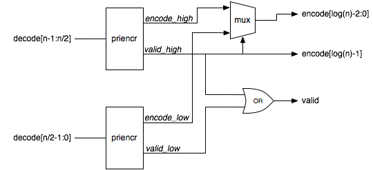
For an encoder which is 2n-bits wide, we could join two 2n-1 bit wide priority encoders together like this.

Recursive implementation of a priority encoder

Recursive implementation of a priority encoder

Verilog code

So what does the code for this look like? It’s pretty simple. If the input vector is two bits wide, then we just implement the base case. Otherwise, if the width is not a power of two, then we pad out the input with zero bits to the next power of two width and then instantiate a power of two width encoder. If the width is a power of two, then we build the encoder out of two encoders half the size.


module priencr #(parameter width = 64)
  (
   input [width-1:0] decode,
   output [log2(width)-1:0] encode,
   output valid
   );

  function [31:0] log2;
    input reg [31:0] value;
    begin
      value = value-1;
      for (log2=0; value>0; log2=log2+1)
	value = value>>1;
    end
  endfunction

  generate
    if (width == 2)
      begin
	assign valid = |decode;
	assign encode = decode[1];
      end
    else if (width & (width-1))
      priencr #(1<<log2(width)) priencr ({1<<log2(width) {1'b0}} | decode,
                                         encode,valid);
    else
      begin
	wire [log2(width)-2:0] encode_low;
	wire [log2(width)-2:0] encode_high;
	wire valid_low, valid_high;
	priencr #(width>>1) low(decode[(width>>1)-1:0],encode_low,valid_low);
	priencr #(width>>1) high(decode[width-1:width>>1],encode_high,valid_high);
	assign valid = valid_low | valid_high;
	assign encode = valid_high ? {1'b1,encode_high} : {1'b0,encode_low};
      end
  endgenerate
endmodule

Wrap up

The only gotchas with recursion are vendor support. I have come across vendors who don’t think recursion is possible in Verilog 2001 because the standard doesn’t say it is specifically supported. The Verilog 2005 standard is very clear that recursion is allowed to help with this problem.

Recursion can be a very powerful way to express tree-like structures in hardware.